KB21 Service Manual Pub 09-14
58
Cylinder Control Systems
40-A. Bucher L.8S Manual Control/Cable
Slide the cable eye into the slot in the spool and
align the holes. Insert the connection pin and install
the retaining pin into the hole in the connecting pin
and secure by bending both ears of the retaining
pin back and around the connecting pin.
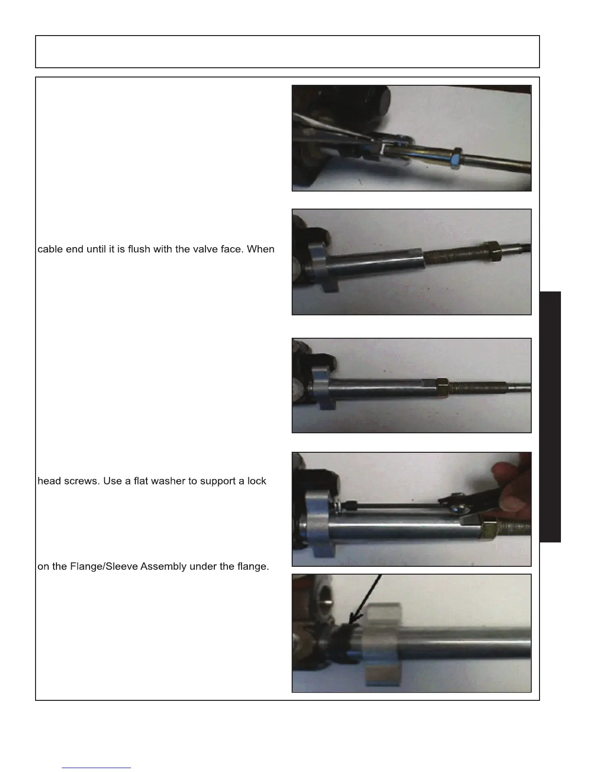
With the cable attached to the valve, turn the
Flange/Sleeve Assembly back onto the threaded
turning on the assembly, make sure that the valve
spool remains in the neutral position.
Tighten the Jam Nut onto the Flange/Sleeve
Assembly to lock it into position.
Tighten the Flange into position using the two Allen
washer on each bolt.
Interference will occur between the Flange/Sleeve
Assembly and the casting of the Inlet Section on
the Valve Section next to the Inlet Section. To
compensate, the provided shims should be placed
Each cable is controlled by the operator with the
use of single axis control handle assemblies.
A single control handle assembly is required to
operate each individual valve section.