25
Electric welding
If electric welding is to be done on the machine or equip-
ment coupled to the machine, both battery cables must be
disconnected.
Connect the return lead of the welding set as close as pos-
sible to the location of the weld.
Jump starting with booster battery
When jump starting with a booster battery, observe the follo-
wing. Check that the booster battery has the correct voltage.
Let the battery in Terri remain connected up. Connect the
jump lead from the positive (+) pole on the booster battery
to the positive (+) pole on the Terri battery, and then connect
the other jump lead from the negative (-) pole on the booster
battery to the negative (-) pole on the Terri battery.
When the engine has started, rst remove the jump lead bet-
ween the positive (+) poles and then the jump lead between
the negative (-) poles.
Caution! Due to the current inrush the batteries may
burst if a fully charged battery is wrongly connected to a
fully discharged one.
Fuses
The fuses protect the electrical circuits against overloading.
The fusebox is located to the right, below the engine hood.
LIST OF FUSES
1-3. Spare
4. Engine stop coil
5. Trailer drive, Trailer brake
6. Main beams
7. Dip beams
8. Position light, left-hand, tail light, cab, tail
light trailer, right hand, instrument panel
lights
9. Position light, right-hand, rear light trailer,
right-hand, instrument panel lightning
10. Signal horn, working light, rear, rotating warning
light
11. Working lights, side
12. Fuel pump, stop lights, ventilation blower, wind-
screen washer, direction indicators, windscreen
and rear window wipers, oil level light, oil pressure
light, differential lock light, oil temperature gauge,
fuel gauge, cooling water temperature gauge
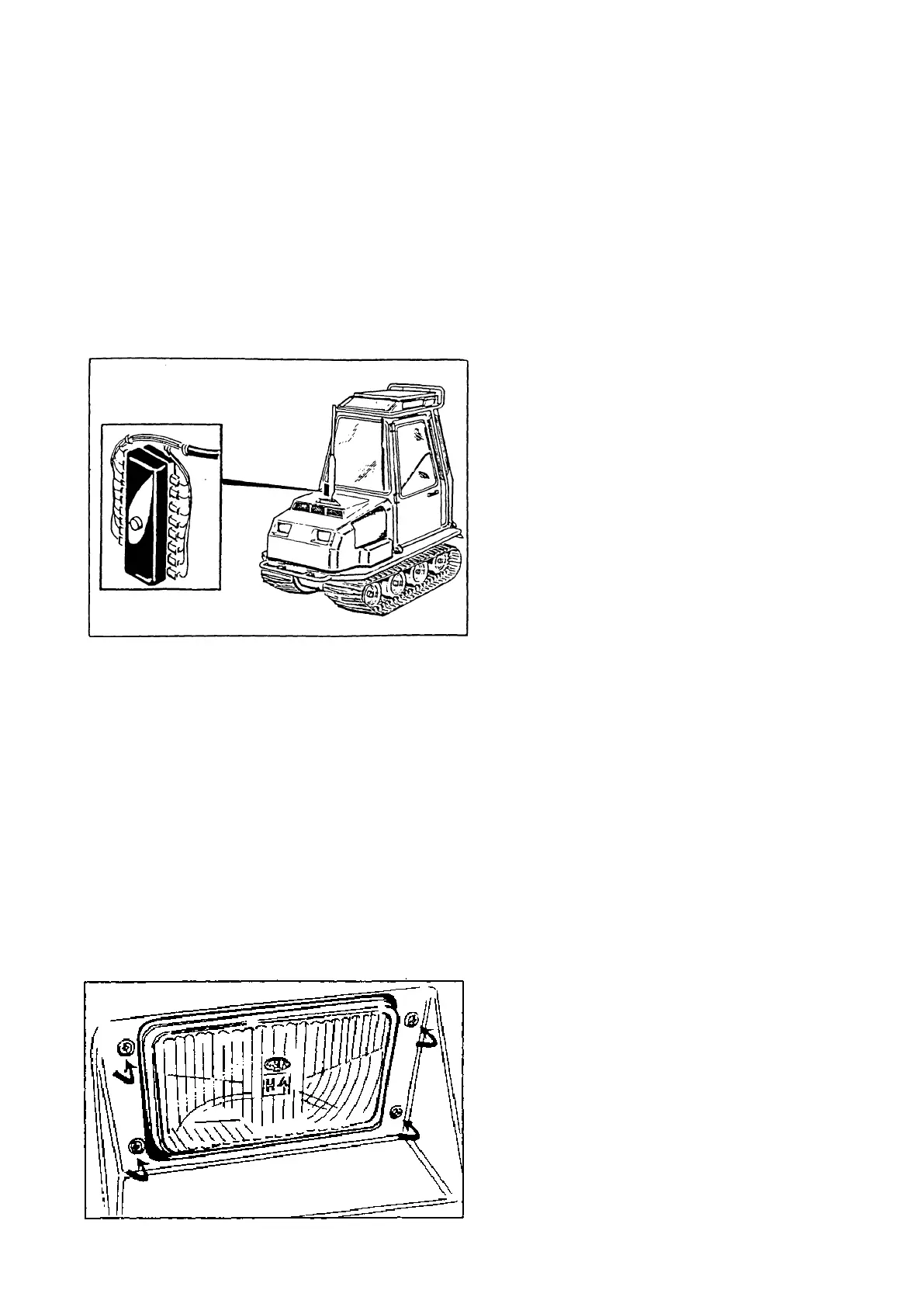
Adjusting of headlights
The headlights are secured with four xing screws, which
at the same time serve as adjusting screws. When the lower
screws are slackened, the light beam is lowered. When, for
example, the left-hand screws are tightened, the light beam
moves to the left.