~~-~~~~~~~~-
~
945424-9701
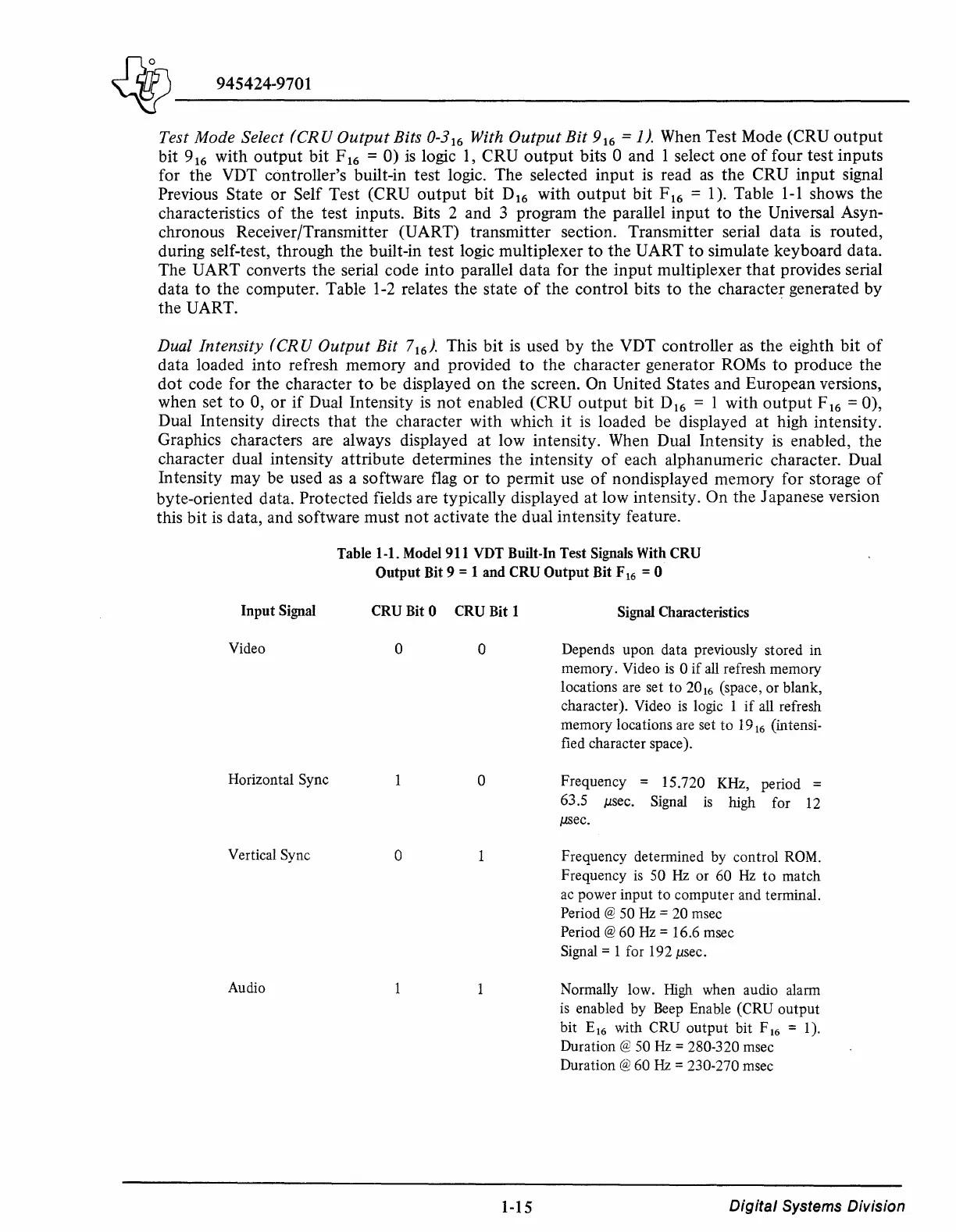
Test Mode Select
(CRU
Output
Bits 0-3
16
With
Output
Bit
9
16
=1). When Test Mode (CRU
output
bit 9
16
with
output
bit F
16
= 0)
is
logic
1,
CRU
output
bits 0 and 1 select one
of
four test inputs
for the VDT controller's built-in test logic. The selected input
is
read
as
the CRU input signal
Previous State
or
Self Test (CRU
output
bit D
16
with
output
bit F
16
= 1). Table
1-1
shows the
characteristics
of
the test inputs. Bits 2 and 3 program the parallel input to the Universal Asyn-
chronous Receiver/Transmitter (UART) transmitter section. Transmitter serial data
is
routed,
during self-test, through the built-in test logic multiplexer to the UART
to
simulate keyboard data.
The UART converts the serial code into parallel data for the input multiplexer
that
provides serial
data
to
the computer. Table
1-2
relates the state
of
the control bits
to
the character generated by
the UART.
Dual Intensity (CRU
Output
Bit
7
16
).
This bit
is
used by the VDT controller
as
the eighth bit
of
data loaded into refresh memory and provided to the character generator
ROMs
to produce the
dot
code for the character
to
be displayed on the screen.
On
United States and European versions,
when set
to
0,
or
if
Dual Intensity
is
not
enabled (CRU
output
bit D
16
= 1 with
output
F
16
= 0),
Dual Intensity directs that the character with which
it
is
loaded be displayed at high intensity.
Graphics characters are always displayed at low intensity. When Dual Intensity
is
enabled, the
character dual intensity attribute determines the intensity
of
each alphanumeric character. Dual
Intensity may be used
as
a software
flag
or
to permit use
of
nondisplayed memory for storage
of
byte-oriented data. Protected fields are typically displayed at low intensity. On the Japanese version
this bit
is
data, and software must
not
activate the dual intensity feature.
Input
Signal
Video
Horizontal Sync
Vertical Sync
Audio
Table 1-1. Model 911 VDT Built-In Test Signals With
CRU
Output
Bit 9 = 1
and
CRU
Output
Bit F
16
= 0
CRU Bit 0 CRU Bit 1
0 0
0
0
1-15
Signal Characteristics
Depends
upon
data previously stored in
memory.
Video
is
0
if
all refresh
memory
locations are set
to
20
16
(space,
or
blank,
character). Video
is
logic 1
if
all refresh
memory
locations are set
to
19
16
(intensi-
fied character space).
Frequency = 15.720 KHz, period =
63 .5
µsec.
Signal
is
high for 12
µsec.
Frequency determined by control ROM.
Frequency
is
50 Hz
or
60
Hz
to
match
ac power
input
to
computer
and terminal.
Period @ 50 Hz = 20 msec
Period@
60
Hz=
16.6 msec
Signal = 1 for 192
µsec.
Normally low.
High
when audio alarm
is enabled
by
Beep Enable (CRU
output
bit
E
16
with CRU
output
bit
F
16
= 1 ).
Duration @ 50 Hz = 280-320 msec
Duration@
60
Hz=
230-270 msec
Digital
Systems Division