~--~9_4_54_2_4_-9_7_0_1~--------~--------------------------------------~
Table
1=2.
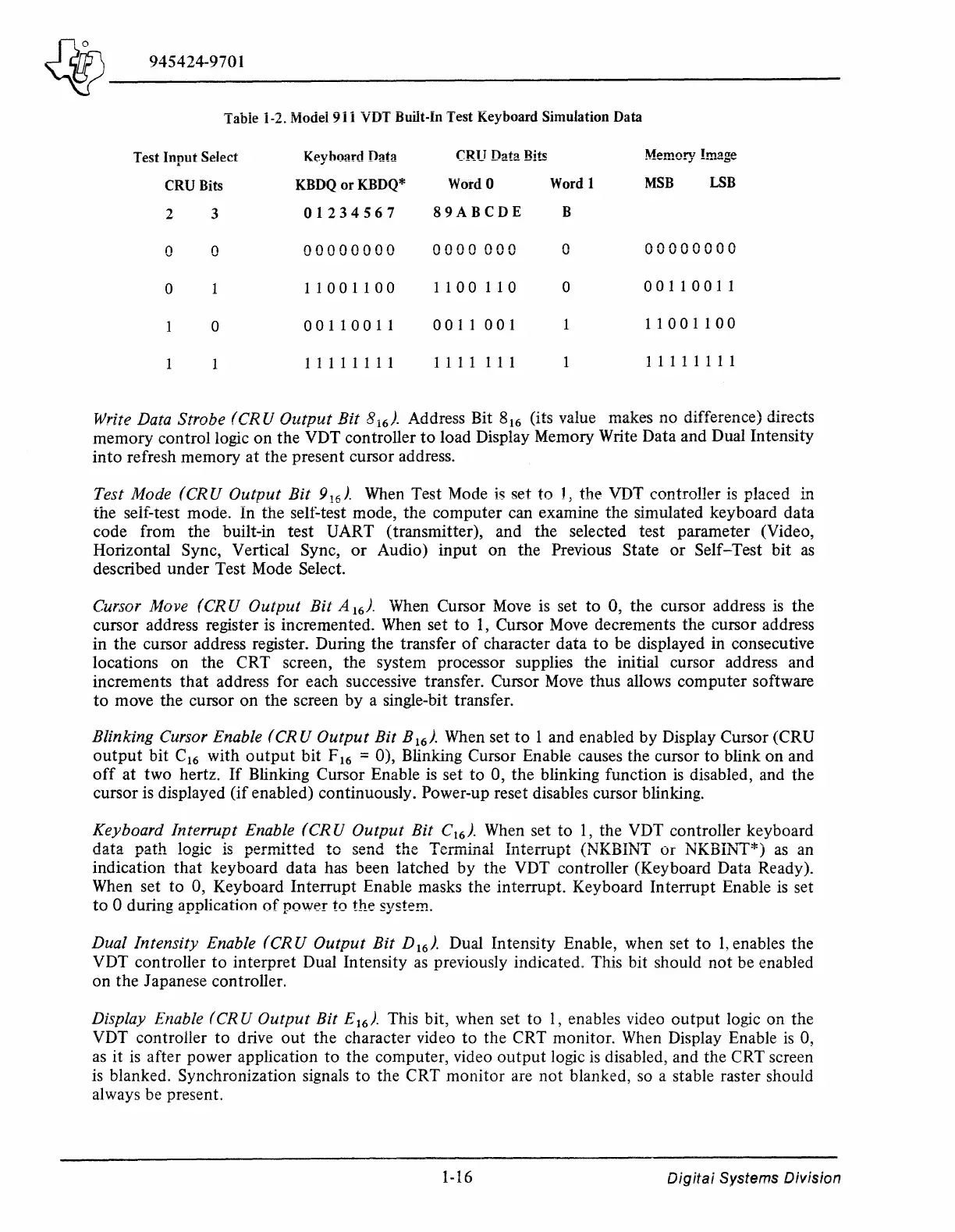
Model 911 VDT Built-In Test Keyboard Simulation Data
Test
Input
Select
Keyhoard Data
CRU Data Bits
CRU Bits
KBDQ
or
KBDQ*
WordO
Word 1
MSB
LSB
2 3
01234567
89ABCDE
B
0
0
00000000
0000
000
('\
v
00000000
0
11001100
1100110
0
00110011
0
00110011
0011
001
11001100
1 1 1 1 1 1 1 1
1 1 1 1
1 1 1
1 1 1 1 1 1 1 1
Write Data Strobe (CR U
Output
Bit
8
16
).
Address Bit 8
16
(its value makes no difference) directs
memory control logic on the VDT controller
to
load Display Memory Write Data and Dual Intensity
into refresh memory at the present cursor address.
Test Mode
(CRU
Output
Bit
9
16
).
When
Test Mode
is
set
to
J,
the VDT controller
is
placed in
the seif-test mode. In the self-test mode, the computer can examine the simulated keyboard data
code from the built-in test UART (transmitter), and the selected test parameter (Video,
Horizontal Sync, Vertical Sync,
or
Audio) input on the Previous State
or
Self-Test bit
as
described under Test Mode Select.
Cursor Move (CR U
Output
Bit
A
16
).
When Cursor
Move
is set
to
0, the cursor address
is
the
cursor address register
is
incremented.
When
set to
1,
Cursor
Move
decrements the cursor address
in the cursor address register. During the transfer
of
character data
to
be displayed in consecutive
locations on the CRT screen, the system processor supplies the initial cursor address and
increments
that
address for each successive transfer. Cursor
Move
thus allows computer software
to
move the cursor on the screen by a single-bit transfer.
Blinking Cursor Enable (CR U
Output
Bit
B
16
l When set
to
1 and enabled by Display Cursor (CRU
output
bit C
16
with
output
bit F
16
= 0), Blinking Cursor Enable causes the cursor to blink on and
off
at two hertz.
If
Blinking Cursor Enable
is
set
to
0, the blinking function
is
disabled, and the
cursor is displayed (if enabled) continuously. Power-up reset disables cursor blinking.
Keyboard Interrupt Enable
(CRU
Output
Bit
C
16
).
When set to
1,
the VDT controller keyboard
data path logic
is
permitted to send the Terminal Interrupt (NKBINT
or
NKBiNT*)
as
an
indication that keyboard data has been latched by the VDT controller (Keyboard Data Ready).
When set to 0, Keyboard Interrupt Enable masks the interrupt. Keyboard Interrupt Enable
is
set
to
0 during application
of
power to the system.
Dual Intensity Enable (CR U
Output
Bit
D
16
).
Dual Intensity Enable, when set
to
1,
enables the
VDT controller
to
interpret Dual Intensity
as
previously indicated. This bit should not be enabled
on the Japanese controller.
Display Enable (CR U
Output
Bit
E
16
).
This bit, when set to
1,
enables video output logic on the
VDT controller to drive out the character video
to
the CRT monitor.
When
Display Enable
is
0,
as
it
is
after power application to the computer, video
output
logic
is
disabled, and the CRT screen
is
blanked. Synchronization signals to the CRT monitor are not blanked,
so
a stable raster should
always be present.
1-16
Digitai Systems Division