~~------------------
~
945424-9701
+SVDC
R38
NC
11
CONTROL
OUTPUT
~-..._-1-----------1
TBRLD-
-5VL3
1/2
NE556V
z D
10
RESET
DISCHARGE
13
----
U17
TRIG
TH
RES
R39
12
F~i'~-
_K_B_S_IN-4-------1---ICLK
Q
BOARD
F~i'~
REPEAT-
BOARD
(A)136275A
STROBE
FLIP-FLOP
CLR
13
CLR
----ID
Q
U17
-
Q
10
REPEAT
FLIP-FLOP
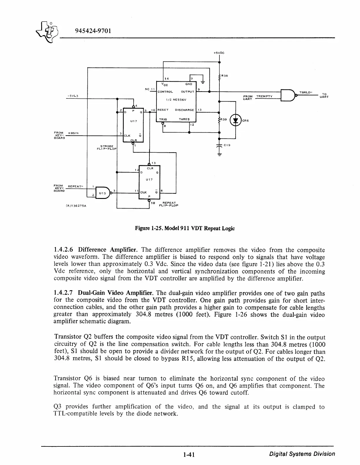
Figure 1-25. Model 911 VDT Repeat Logic
FROM
TREMPTY
UART
CR6
TO
UART
1.4.2.6 Difference Amplifier. The difference amplifier removes the video from the composite
video waveform. The difference amplifier
is
biased
to
respond only
to
signals
that
have voltage
levels lower than approximately 0.3 Vdc. Since the video data (see figure 1-21) lies above the 0.3
Vdc reference; only the horizontal and vertical synchronization components
of
the incoming
composite video signal from the VDT controller are amplified
by
the difference amplifier.
1.4.2. 7 Dual-Gain Video Amplifier. The dual-gain video amplifier provides one
of
two gain paths
for the composite video from the VDT controller. One gain
path
provides gain for short inter-
connection cables, and the
other
gain
path
provides a higher gain
to
compensate for cable lengths
greater than approximately 304.8 metres
(I
000 feet). Figure I
~26
shows the dual-gain video
amplifier schematic diagram.
Transistor Q2 buffers
the
composite video signal from the VDT controller. Switch SI in the
output
circuitry
of
Q2
is
the line compensation switch.
For
cable lengths less than 304.8 metres
(I
000
feet), S 1 should be open
to
provide a divider network for the
output
of
Q2.
For
cables longer than
304.8 metres, S 1 should be closed
to
bypass
RI
5, allowing less attenuation
of
the
output
of
Q2.
Transistor Q6
is
biased near turnon to eliminate the horizontal sync component
of
the video
signal. The video component
of
Q6's input turns Q6 on, and Q6 amplifies
that
component. The
horizontal sync component
is
attenuated and drives Q6 toward cutoff.
Q3
provides further amplification
of
the video, and the signal at its
output
is
clamped to
TTL-compatible levels by the diode network.
1-41
Digital
Systems Division