~
945424-9701
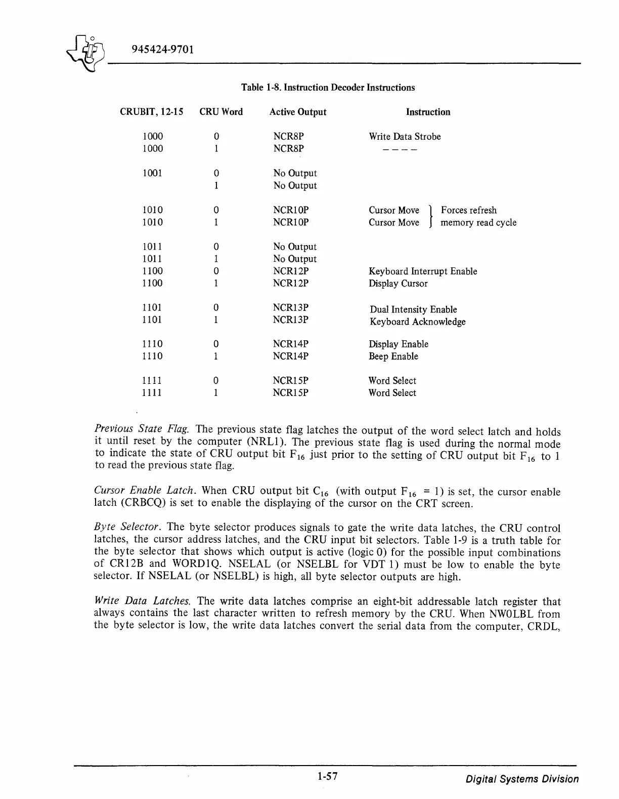
Table 1-8. Instruction Decoder Instructions
CRUBIT, 12-15
CRUWord
Active
Output
Instruction
1000
0
NCR8P
Write Data Strobe
1000 NCR8P
----
1001
0
No Output
No Output
1010
0 NCRlOP Cursor
Move
}
Forces refresh
1010 1 NCRlOP
Cursor
Move
memory read cycle
1011
0
No Output
1011 1 No Output
1100 0 NCR12P
Keyboard Interrupt Enable
1100 1 NCR12P
Display Cursor
1101
0
NCR13P
Dual Intensity Enable
1101
NCR13P
Keyboard Acknowledge
1110
0 NCR14P Display Enable
1110
1 NCR14P Beep Enable
1111
0
NCRlSP
Word Select
1111 1 NCR15P Word Select
Previous State
Flag.
The previous state flag latches the
output
of
the word select latch and holds
it until reset by the computer (NRLI
).
The previous state flag
is
used during the normal mode
to indicate the state
of
CRU
output
bit
F
16
just prior
to
the setting
of
CRU
output
bit F
16
to
1
to
read the previous state
flag.
Cursor Enable Latch. When CRU
output
bit C
16
(with
output
F
16
=
1)
is
set, the cursor enable
latch (CRBCQ)
is
set
to
enable the displaying
of
the cursor on the CRT screen.
Byte
Selector. The byte selector produces signals
to
gate the write data latches, the CRU control
latches, the cursor address latches, and the CRU input bit selectors. Table
1-9
is
a
truth
table for
the byte selector
that
shows which
output
is
active (logic 0) for the possible input combinations
of
CR12B and WORDlQ. NSELAL (or NSELBL for VDT 1) must be low to enable the byte
selector.
If
NSELAL (or NSELBL)
is
high, all byte selector
outputs
are high.
Write Data Latches. The write data latches comprise an eight-bit addressable latch register
that
always contains the last character written
to
refresh memory by the CRU.
When
NWOLBL
from
the byte selector
is
low, the write data latches convert the serial data from the computer, CRDL,
1-57
Digital
Systems Division