www.ti.com
Hardware Low Power Design Guidelines
3
SPRAC74A–February 2017–Revised March 2017
Submit Documentation Feedback
Copyright © 2017, Texas Instruments Incorporated
AM335x Low Power Design Guide
When selecting a PMIC, refer back to the power tree to make sure the outputs of the PMIC can satisfy the
voltage and power requirements of the identified voltage supply rails. In many cases, rails can be sourced
from the same PMIC output as long as they are of the same voltage and the total current draw is less than
the maximum output current of the PMIC. In some cases where other devices on a system consume large
amounts of power, it makes sense to use the PMIC primarily as a power supply for the processor, and use
an alternative power solution to power the rest of the device.
In addition to checking to make sure that the PMIC or power supply chosen satisfies the power
requirements, special consideration must be made for specific use cases. For example, DDR3L requires a
1.35 V supply rail, and if Real-Time Clock (RTC) mode is to be supported, the PMIC must allow for a
configuration where it is on during suspend. Finally, a balance between cost and power efficiency must be
made since some PMIC features may come at increased cost.
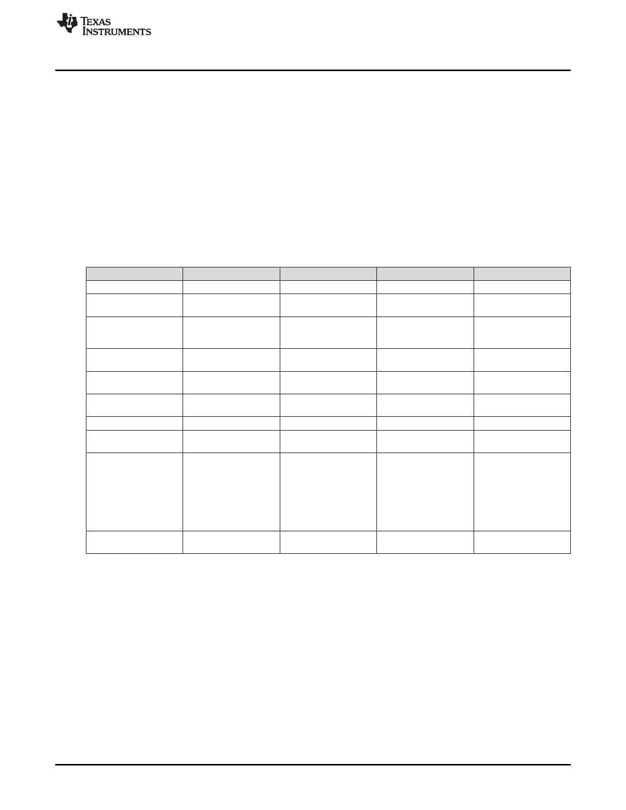
2.1.2 Recommended PMICs
Table 1. Recommended PMICs
Feature TPS650250 TPS65217 TPS65910 TPS65218
Power (DCDC/LDO) 3 DCDC/ 3 LDO 3 DCDC/ 2 + 2 LDOs 3 DCDC/ 9 LDO 4 + 2 DCDC / 1 LDO
Voltage Range 2.5 - 6.0 V 2.75 - 5.5 V (20 V
Tolerant)
2.7 - 5.5 V 2.75 - 5.5 V
Dynamic Voltage
Scaling OPP Supported
No
300/ 600 MHz
Yes
300/ 600/ 720/ 800/
1000 MHz
Yes
300/ 600/ 720/ 800/
1000 MHz
Yes
300/ 600/ 720/ 800/
1000 MHz
Supervisor No No No Yes
(± 4%, ± 5%)
Power Sequencing No
Requires external circuit
Yes Yes Yes
Memory Support LPDDR1, DDR2, DDR3 LPDDR1, DDR2,DDR3,
DDR3L
LPDDR1, DDR2, DDR3 LPDDR1, DDR2, DDR3,
DDR3L
Battery Charger No Linear w/ Power-Path No No
RTC No (requires external
LDO)
No Yes No uP controls power to
RTC
Other features Power fail comparator
• WLED Driver
• 2 LDO can be
configured as load
switches
• I2C Interface
• 5 V Boost (100 mA)
• 2x I2C Interface
• Three load
switches
• Power fail
comparator
• Supports warm
reset
• I2C Interface
Temperature Range -40, 85°C/ -40, 125°C
(Q1)
-40, 105°C -40, 85°C -40, 105°C
2.2 I/O Considerations
I/O configuration is very important when designing a system for low power. Properly configured I/O will
minimize static leakage current from misconfigured pull-up/ pull-down networks, improper termination, as
well as maximizing functionality by enabling built-in power saving features on the AM335x.
In addition, for low power use cases, consider using 1.8 V I/O where possible; reducing the switching
voltage significantly reduces system power consumption.
2.2.1 Pin configuration
I/O planning can be done using the pinmux tool that is both available as a constantly updated cloud tool,
or as a downloadable program for Windows
®
and Linux
®
. This tool generates relevant configuration files
for software to configure I/Os on the AM335x as intended. It is important to note that the hardware
configuration in the design and configuration done in software match in order to prevent leakage current.
Software configurations are discussed in the Linux power management section.

 Loading...


