www.ti.com
Hardware Low Power Design Guidelines
5
SPRAC74A–February 2017–Revised March 2017
Submit Documentation Feedback
Copyright © 2017, Texas Instruments Incorporated
AM335x Low Power Design Guide
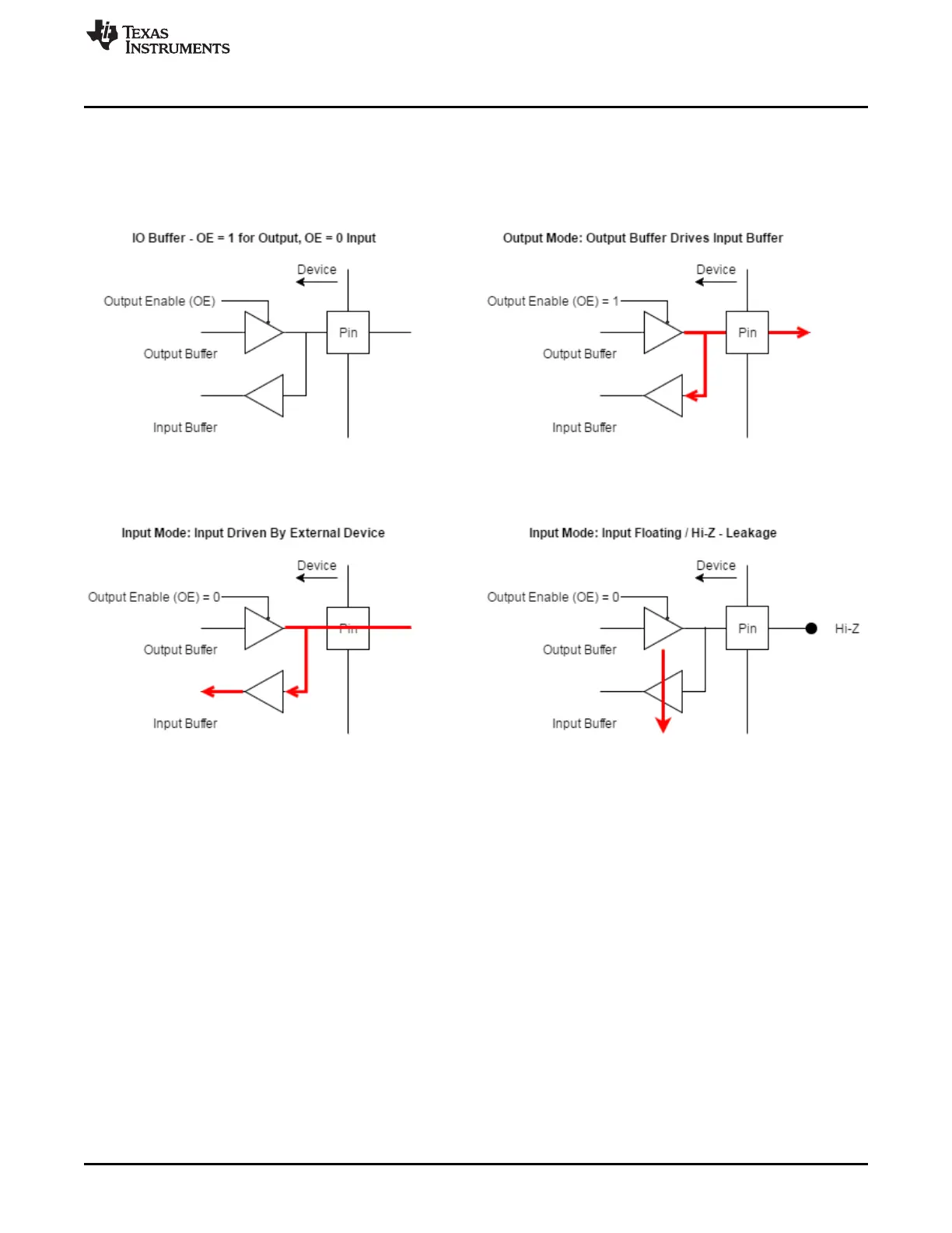
2.2.1.2 GPIO Leakage Scenarios
I/O buffers are implemented with two buffers: an output buffer with an enable signal and an input buffer.
The enable line is controlled by internal logic and the specific implementation of the enable signal is
device specific. When the output buffer is enabled, it drives the input buffer, but when the pin is configured
as an input, the pin must be driven or else the input buffer will be floating and can draw leakage current.
Figure 2. GPIO Leakage Scenarios
2.2.1.3 Internal Pull Up / Down
The internal pull-up/pull-down resistors are implemented with weak transistors. Since the effective
resistance of these "resistors" vary according to their gate voltage, the internal pull up/down resistors will
not consume additional power if the internal and external pulls match. To prevent excessive static power
consumption, be sure that there are no pin conflicts between the board schematic and the internal
configuration of the AM335x. Inputs that can be in a high impedance (Hi-Z) state should have an
appropriate pull up/down resistor to accommodate for the times when the input is not driven.
Of the cases in the diagram below, only Case 5 will register as device static power consumption since the
processor is sourcing current. However, both Case 5 and Case 6 have static leakage current, Case 6 just
consumes power from an external power rail.
Ensure all pullups connected to AM335x are pulled up to the correct I/O voltage to avoid any leakage
between the I/O rails of AM335x. Also ensure that the system generates inputs either below V
IL
or above
V
IH
. For example, a 1.8 V peripheral connected to a 3.3 V input will be in between V
IL
and V
IH
when the 1.8
V signal is high. This means that not only will the peripheral not work properly, it causes the processor to
consume extra power.
A mid-supply will have a big effect on power consumption. Each terminal has an associated voltage used
to power its I/O cell, the corresponding voltage rail for each pin can be found in the AM335x Sitara™
Processors Data Manual, in the Ball Characteristics table under the "ZCE Power/ ZCZ Power" column.

 Loading...


