Hardware Low Power Design Guidelines
www.ti.com
4
SPRAC74A–February 2017–Revised March 2017
Submit Documentation Feedback
Copyright © 2017, Texas Instruments Incorporated
AM335x Low Power Design Guide
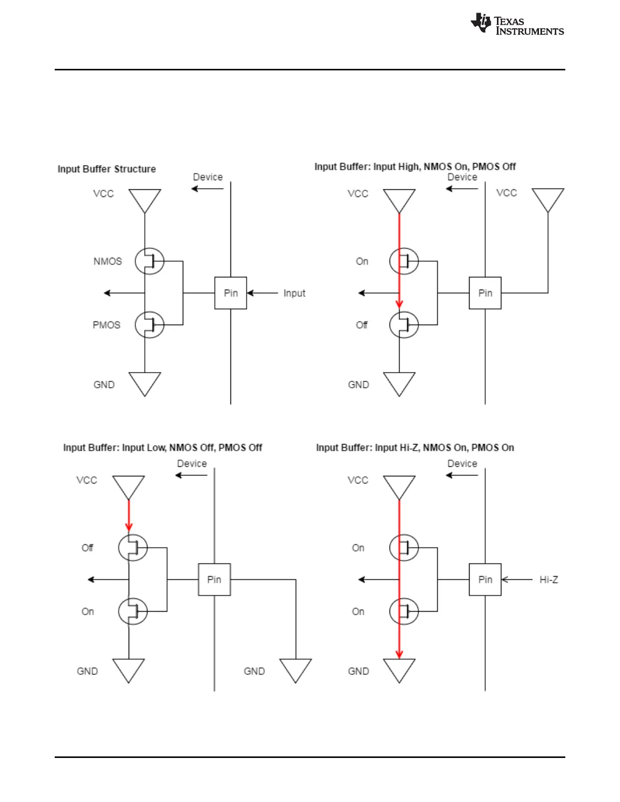
2.2.1.1 Input Buffer Leakage
Input buffers are implemented as two CMOS transistors between V
CC
and ground. When an input is driven
either high or low, only one of these transistors will be switched on, and there is no leakage current.
However, if the input is floating, or in a high impedance state, sometimes the voltage at the input can be
between V
IL
and V
IH
(the points where an input is considered either low or high, respectively); in this state,
both transistors are partially switched on creating a resistive path to ground.
Figure 1. Input Buffer

 Loading...


