3.1 Functional Description and Connections
3.1.1 Microcontroller
The TMS320F280039CSPZ is a 32-bit floating-point microcontroller with 384KB Flash memory, 69KB RAM,
a programmable Control Law Accelerator (CLA) for offloading tasks, and operates at 120 MHz. It includes
advanced control peripherals, differentiated analog, and various communications peripherals. The device has
been optimized for high-performance real-time control applications. For more details, see the TMS320F28003x
Real-Time Microcontrollers Data Sheet.
Most of the microcontroller's signals are routed to 0.1 inch (2.54 mm) pitch headers laid out to comply with
the TI BoosterPack standards, with a few exceptions. The F28003x MCU's internal multiplexer allows different
peripheral functions to be assigned to each of the General-Purpose Input/Output (GPIO) pins. The multiplexing
options can be found in the device-specific data sheet. When adding external circuitry, consider the additional
load on the development board's power rails.
The F28003x LaunchPad is factory-programmed with a quick start demo program. The quick start program
resides in the on-chip Flash memory and executes each time power is applied, unless the application has been
replaced with a user program. For details on the LaunchPad's demo program, see Section 2.2.
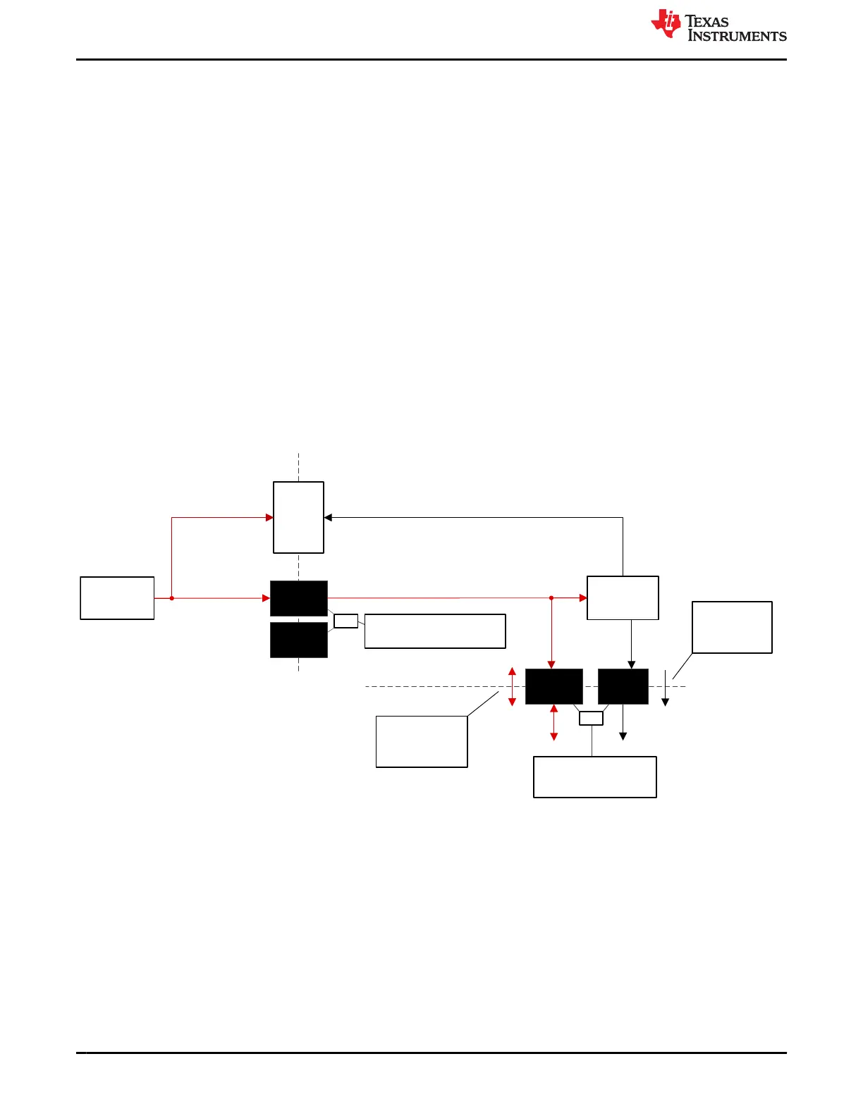
3.1.2 Power Domains
The F28003x LaunchPad has several power domains that can be connected or isolated from each other with
removable shunts. The different 3.3 V and 5 V power domains are further described in Figure 3-2 and Figure
3-3.
USB Type-C™
Conn
USB
Isolator
Device
3.3-V Power
Management
+3V3
Shunt
5-V & 3.3-V Isolation
Boundary
+5V0
Shunt 1
+5V0
Shunt 2
PWR & GND
Isolation Boundary
+3V3_MCU
XDS110 Side
MCU Side
+5V0 and GND shunts to enable
or break isolation boundary
Shunts to disconnect +5 V
and/or +3.3 V between
XDS110 and MCU sides
+3.3-V power
only flows from
XDS110 to MCU
side
+5-V power can flow
from either the
XDS110 or MCU
sides
GND
Shunt
+5V0_MCU
JP1
JP2
+5V0_USB +5V0_XDS110
+3V3_XDS110
+5V0 +3V3
+3V3_XDS110
Figure 3-2. LaunchPad Power Distribution Diagram
Hardware Description www.ti.com
10 C2000
™
F28003x Series LaunchPad
™
Development Kit SPRUJ31 – APRIL 2022
Submit Document Feedback
Copyright © 2022 Texas Instruments Incorporated
 Loading...


