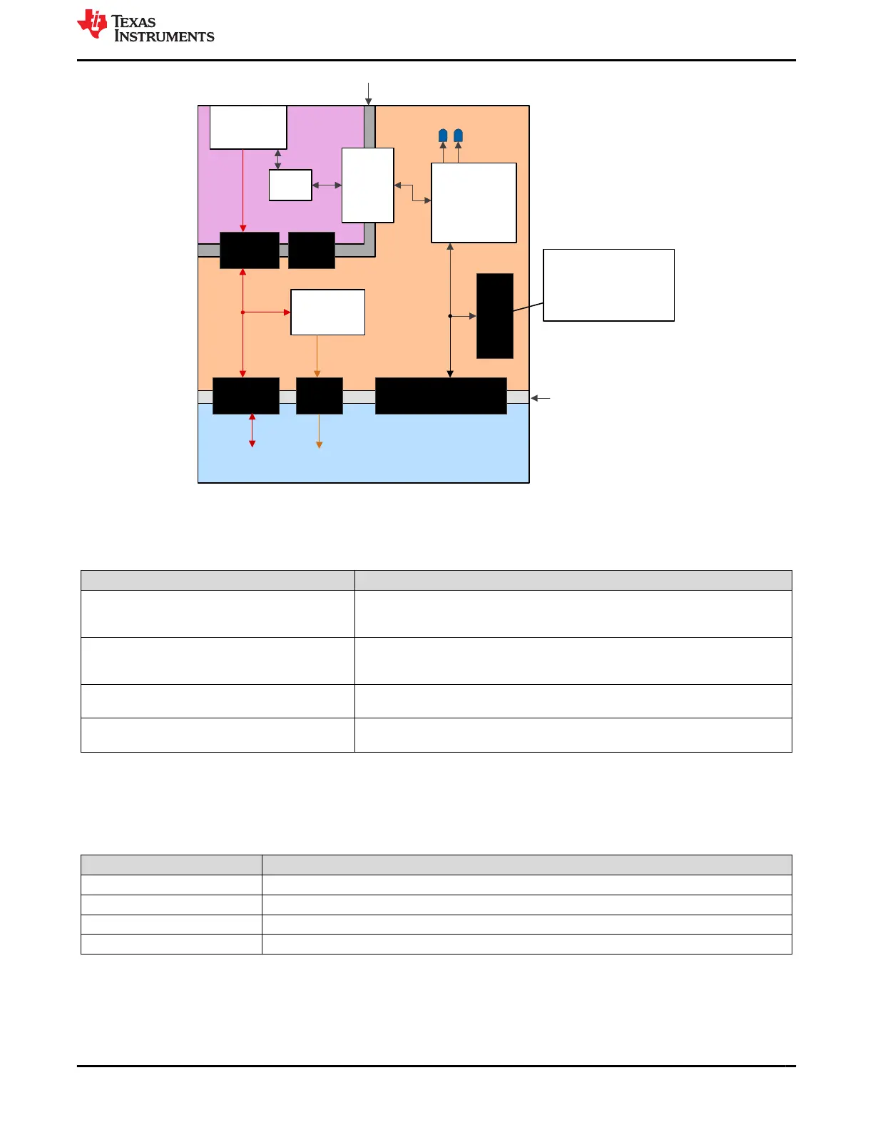
3.3-V Plane 1 (XDS110 side)
USB Type C™
Connection
USB
Isolator
Device
XDS110 – MSP432
device & Circuitry
5V
Shunt 1
3.3-V Power
Management
SCI & JTAG Shunts
USB
ESD
Device
Isolation Boundary
3.3-V & 5-V Isolation
Boundary
+5V0_MCU
5-V Shunt 2
3.3-V
Shunt
XDS110 14-pin
Connector
+3V3_MCU
GND
Shunt
5 V and USB Plane
3.3-V Plane 2
(F28003x side)
Connector Supports the
Following:
4-pin JTAG
XDS110 Reset OUT
UART/SCI
3.3-V PWR / GND
Figure 3-3. LaunchPad Power Plane Diagram
Table 3-1 describes the usage of the different removable shunts on the LaunchPad board.
Table 3-1. Power Domain Shunts
Shunt Identifier Usage Description
JP1, +5V0
Connects the +5 V power from the USB-C connector (+5V0_USB) to the +5 V power
on the XDS110 side of the board (+5V0_XDS110). Bridges the power and ground
isolations between the two board sides.
JP1, GND
Connects the board Ground on the isolated USB-C connector side of the board
(USB_GND) to the rest of the board ground (GND). Bridges the power and ground
isolations between the two board sides.
JP2, +5V0 Connects the +5 V power on the XDS110 side of the board (+5V0_XDS110) to the +5
V power on the F280039C side of the board (+5V0_MCU).
JP2, +3V3 Connects the +3.3 V power on the XDS110 side of the board (+3V3_XDS110) to the
+3.3 V power on the F280039C side of the board (+3V3_MCU).
3.1.3 LEDs
Power indicator LEDs (red) are included on the F28003x LaunchPad board. Table 3-2 shows descriptions of
each LED.
Table 3-2. Power LED Indication Descriptions
LED No. Indication Decription:
LED7 +5 V power from the USB Type-C™ connector
LED0 +3.3 V power on the XDS110 side of the PCB
LED1 +3.3 V power on the F28003x side of the PCB
LED6 +5 V power on the F28003x side of the PCB
Two user LEDs are provided on the board: LED4 (red) and LED5 (green). These user LEDs are connected to
GPIO20 and GPIO22 of the F280039C, respectively. The signals are connected to the SN74LVC2G07DBVR
LED driver IC and are connected in an active low configuration; that is, drive the GPIO low to turn on the LED
and high to turn it off. These LEDs are dedicated for use by the software application.
www.ti.com Hardware Description
SPRUJ31 – APRIL 2022
Submit Document Feedback
C2000
™
F28003x Series LaunchPad
™
Development Kit 11
Copyright © 2022 Texas Instruments Incorporated
 Loading...


