3 Hardware Description
The F28003x LaunchPad includes a F280039CSPZ MCU, which is well suited for advanced real-time control
applications. A large number of these peripherals are made available to users via the on-board accessories and
the BoosterPack connectors. This section explains how those peripherals operate and interface to the MCU.
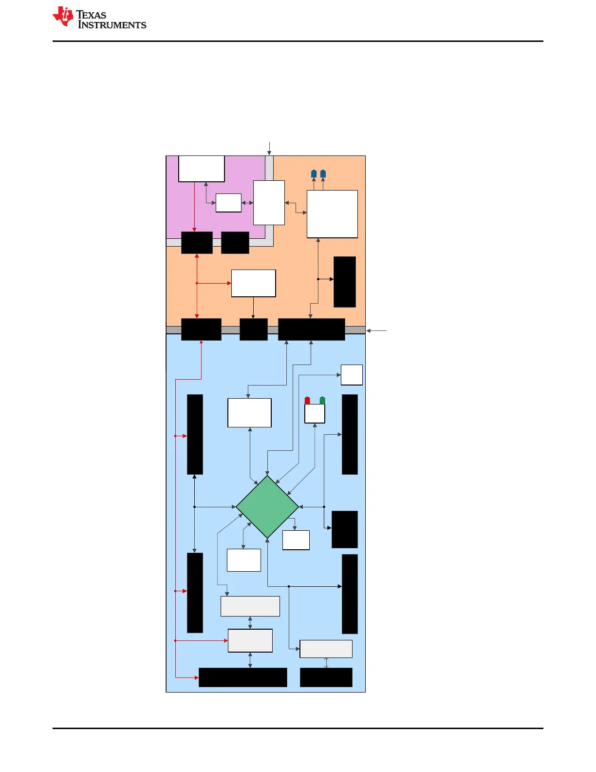
Figure 3-1 shows a high-level block diagram of the F28003x LaunchPad:
USB Type-C™
Connector
USB
Isolator
Device
XDS110 – device &
Circuitry
5V
Shunt 1
3.3-V Power
Management
F280039C Device
UART & JTAG Shunts
USB
ESD
Device
Boot Mode
switch –
GPIO 24/32
2x10-pin BP Header
FSI 2x5
Header
Reset
Button
CAN Header
Crystal
Oscillator
LED
Driver
eQEP 3.3-V 5-V
Level Shifters
eQEP Headers
2x10-pin BP Header
2x10-pin BP Header 2x10-pin BP Header
UART signal
Selection
Circuitry
eQEP Signal Selection
Circuitry
PWR & GND Isolation
Boundary
3.3-V & 5-V Isolation
Boundary
+5V0 (USB side)
+3V3 (XDS110 side)
+3V3_MCU
(F28003x side)
CAN Transceiver
5V Shunt 2
3.3V
Shunt
XDS110 14-pin
Connector
GND
Shunt
+5V0_USB
+5V0_XDS110
+5V0_MCU
+3V3_XDS110
Figure 3-1. F28003x LaunchPad Development Kit Block Diagram
www.ti.com Hardware Description
SPRUJ31 – APRIL 2022
Submit Document Feedback
C2000
™
F28003x Series LaunchPad
™
Development Kit 9
Copyright © 2022 Texas Instruments Incorporated
 Loading...


