2.2.2 Measure the CC35xxE Current Draw
2.2.2.1 Low Current Measurement (LPDS)
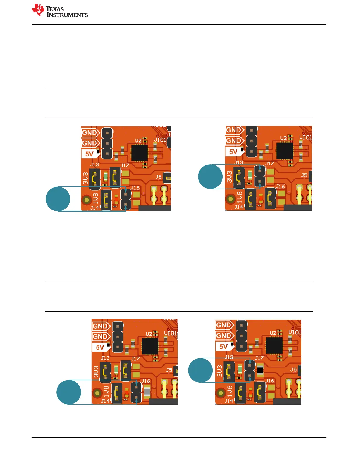
To measure the current draw of the CC35xxE device for both power supplies (3.3V or 1.8V), a jumper labeled
J17 (for 3.3V supply) and a jumper labeled J16 (for 1.8V supply) is provided on the board. By removing J16,
users can place an ammeter into this path to observe the current on the 1.8V supply. The same process can
be used for observing the current on the 3.3V supply with J17. TI recommends this method for measuring the
LPDS.
Note
The current measured on the 3.3V and 1.8V jumpers is the total current that goes to the CC35xxE, not
including VIO1, VIO2, and VDDSF. These supplies provide reference voltage for all of the IOs and to
some of the peripherals on the LP-EM-CC35X1 (ADC buffers, sensors, and so forth.).
Figure 2-22. Low Current Measurement
2.2.2.2 Active Current Measurement
To measure active current of the CC35xxE device in a profile form, TI recommends using a 0.1Ω 1% 0603
resistor on the board, and measuring the differential voltage across the resistor. This can be done using a
voltmeter or an oscilloscope for measuring the current profile for both power supplies (3.3V or 1.8V).
Jumper J16 shunt is removed and a 0.01 resistor is populated in parallel to measure the active currents on the
1.8V supply; see Figure 2-23. Perform a similar operation with J17 and 3.3V supply.
Note
The current measured on the 3.3V and 1.8V jumpers is the total current that goes to the CC35xxE, not
including VIO1, VIO2, and VDDSF. These supplies provide reference voltage for all of the IOs and to
some of the peripherals on the LP-EM-CC35X1 (ADC buffers, sensors, and so forth.).
Figure 2-23. Active Current Measurement
www.ti.com Hardware
SWRU629 – SEPTEMBER 2024
Submit Document Feedback
CC35xxE LaunchPad™ Development Kit for SimpleLink™ Wi-Fi 6 and
Bluetooth® Low Energy Wireless MCU
19
Copyright © 2024 Texas Instruments Incorporated