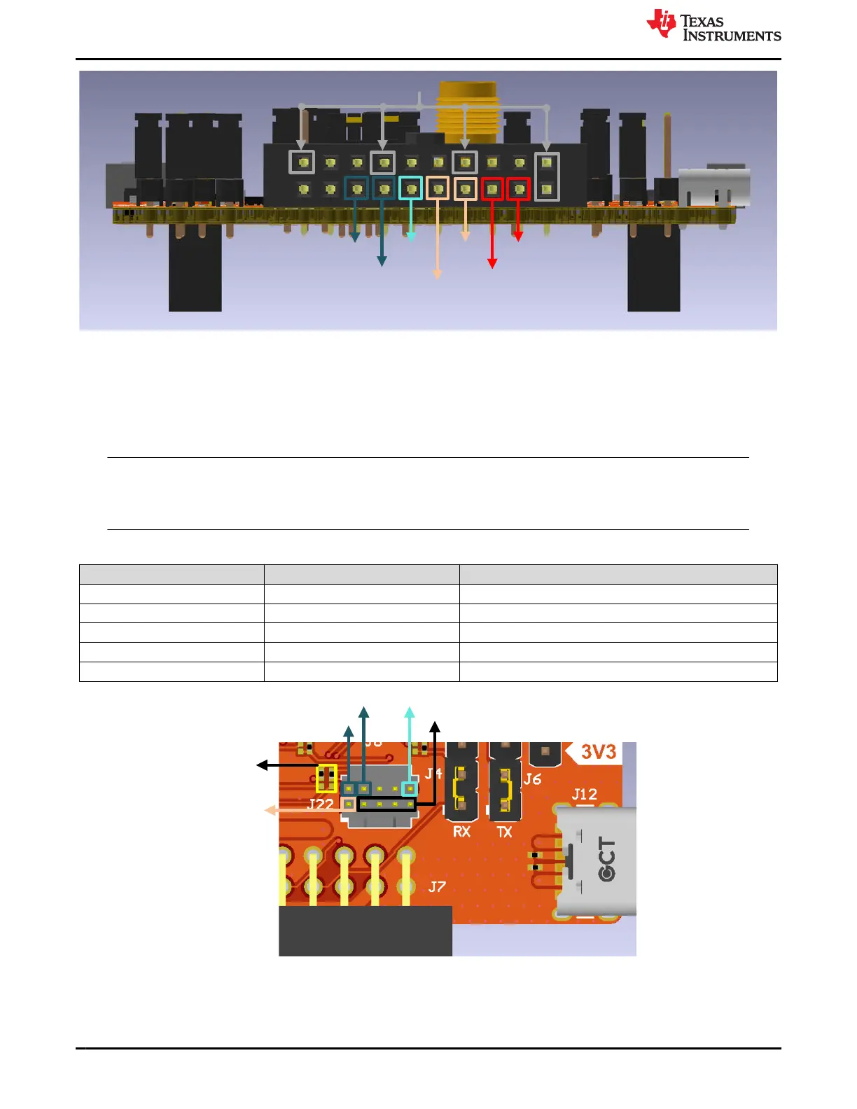
GND
SWCLK
SWDIO
nRESET
UART1_RX
UART1_TX
VIO1
VCC_BRD_5V
Figure 2-3. 20-pin LP-XDS110 Connector (J7)
There is also the option to use the ARM Cortex-M 10-pin (CM10) connector for SWD interface. This connector is
not assembled by default but a CM10 header can be soldered on the J22 footprint on the LP-EM-CC35X1. For
J22 footprint location, see Figure 2-2.
The pinout of the CM10 connector when assembled is shown in Figure 2-4 and Table 2-2.
Note
In addition to assembling the CM10 connector, 0 ohm resisters must change assembly location for
SWD interface to this connector. R106 and R107 must be placed on the top two solder pads instead
of the default bottom two solder pads, as shown in Figure 2-4.
Table 2-2. CM10 Connector (J22) Assignment
Pin Signal Name Description
J22.1 VIO1 VIO1 supply reference voltage to connector
J22.2 SWDIO Serial wire data in/out (See note)
J22.4 SWCLK Serial wire clock (See note)
J22.10 XDS_RESET nRESET (enable line to the CC3551E)
J22.3, J22.5, J22.7, J22.9 GND Board Ground
Pin 1
SWDIO
SWCLK nRESET
GND
R106,
R107
Figure 2-4. CM10 Connector (J22)
Hardware www.ti.com
6 CC35xxE LaunchPad™ Development Kit for SimpleLink™ Wi-Fi 6 and
Bluetooth® Low Energy Wireless MCU
SWRU629 – SEPTEMBER 2024
Submit Document Feedback
Copyright © 2024 Texas Instruments Incorporated