www.ti.com
Interfaces
2.1 Overview
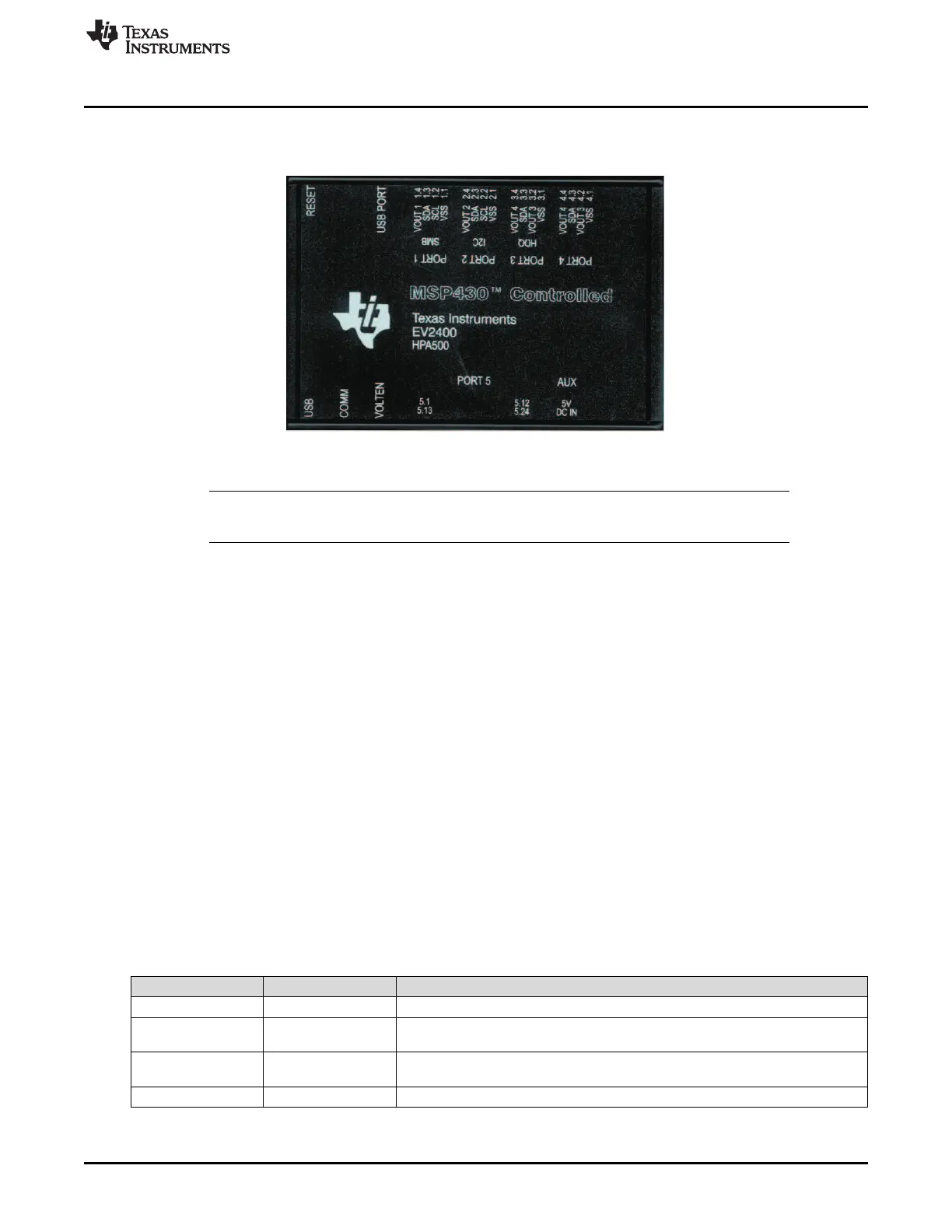
The EV2400 ports are shown in Figure 1.
Figure 1. EV2400 Ports
NOTE: The additional power input 5-V port on the EV2400 must not be connected in normal
operation. Normal operation uses power from the USB port.
2.2 EV2400 Controller
The EV2400 controller is an MSP430F5529 running at 4 MHz. The controller firmware is stored in flash
memory and is executed by the core at power-up.
The controller communicates with target device(s) through either: a 2-wire SMBus communication port or
a 2-wire EEPROM I
2
C port. The 2-wire SMBus communication port supports both SMBus and I
2
C
protocols. CRC-8 checksum verification for the data packets prevents data corruption over the USB.
2.3 USB Interface (USB)
The interface board connects to a USB port (version 1.1 or later) on a host computer and is powered from
the port. All communication over the USB is human Interface device (HID) class. Drivers are built into
Windows
®
and most of the operating systems.
2.4 HDQ Interface (HDQ)
This interface port is not currently supported.
2.5 I
2
C Interface (I
2
C)
This interface allows a host computer to interact with I
2
C interfaces, such as a battery monitor device and
EEPROM through a 2-wire I
2
C interface. Connect the data, clock, and a ground reference (VSS) to a
target device.
Pin Name Description
2.1 VSS Ground return/reference for I
2
C interface.
2.2 SCL I
2
C clock. Pulled up to 3.3 V with a 20-kΩ resistor. Uses bus acceleration in
positive direction to allow for larger pullup.
2.3 SDA I
2
C data. Pulled up to 3.3 V with a 20-kΩ resistor. Uses bus acceleration in positive
direction to allow for larger pullup.
2.4 VOUT 2 Optional voltage output (future expansion)
3
SLUU446B–June 2011–Revised August 2014 EV2400 EVM Interface Board
Submit Documentation Feedback
Copyright © 2011–2014, Texas Instruments Incorporated