• This processes the existing data in the plots, and converts new data coming in. If receiving new
data while changing units, it is possible that a datapoint gets missed or duplicated.
• Max
– The maximum y-axis value to use for all EVMs in this plot.
– If this field is empty when Manual Scale is selected, then it will auto populate with the maximum
value currently in the plot.
• Min
– The minimum y-axis value to use for all EVMs in this plot.
– If this field is empty when Manual Scale is selected, then it will auto populate with the minimum
value currently in the plot.
4.2.3 Current Sensing Operation
The EVM can be used with either an onboard or external shunt resistor. To use the onboard shunt resister,
solder a 2512 surface-mount technology (SMT) shunt resistor across the pads of R1, and connect it in series
with the external system and load current via J1. An external shunt can be connected directly across the
terminals of J1. There are two terminals each for IN+ (J1 pins 5 and 6) and IN– (J1 pins 3 and 4) for
convenience.
4.2.3.1 Detailed Setup
To configure a measurement evaluation, follow these steps:
1. Connect a shunt resister by doing either of the following:
a. Solder a 2512 resistor across the pads of R1 that connects the IN+ and IN– inputs.
b. Connect an external shunt across the IN+ and IN– terminals of J1, preferably across pins 4 and 5, as
shown in Figure 4-14 and Figure 4-15.
i. If an external shunt is being used, make the connections such that the sensing location is across
the shunt and there will be no high current on the sensing path. See the TI Precision Labs - Current
Sense Amplifiers: Shunt Resistor Layout video for more information.
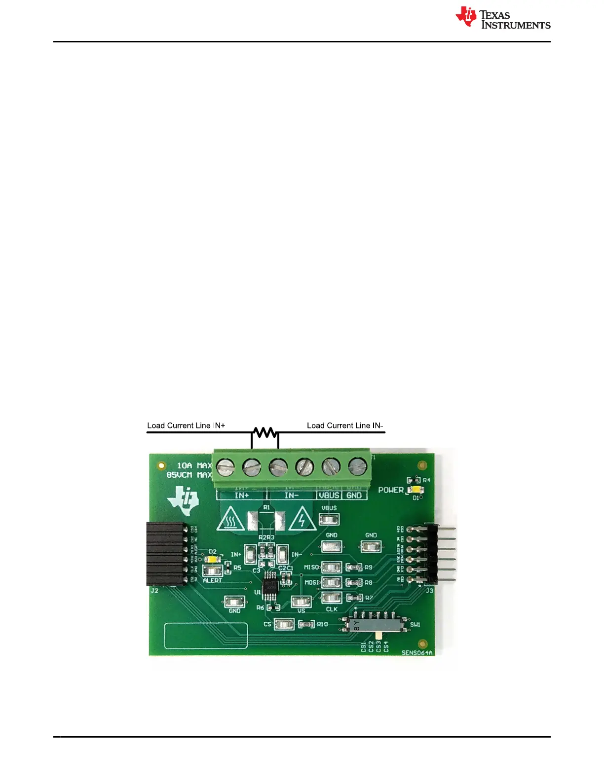
2. Connect the IN+ and IN– terminals in series with the load while powered off.
a. When measuring more than 10 A, make sure the high current path does not go through the EVM
(including the terminal block J1), as shown in Figure 4-14.
Figure 4-14. IN+ and IN– Wiring for More Than 10A
Operation www.ti.com
16 INA228, INA229, INA237, INA238, and INA239 EVM User’s Guide SBOU241C – APRIL 2020 – REVISED JULY 2021
Submit Document Feedback
Copyright © 2021 Texas Instruments Incorporated
 Loading...


