b. When using 10 A or less with either an onboard or external shunt, the current path can be passed
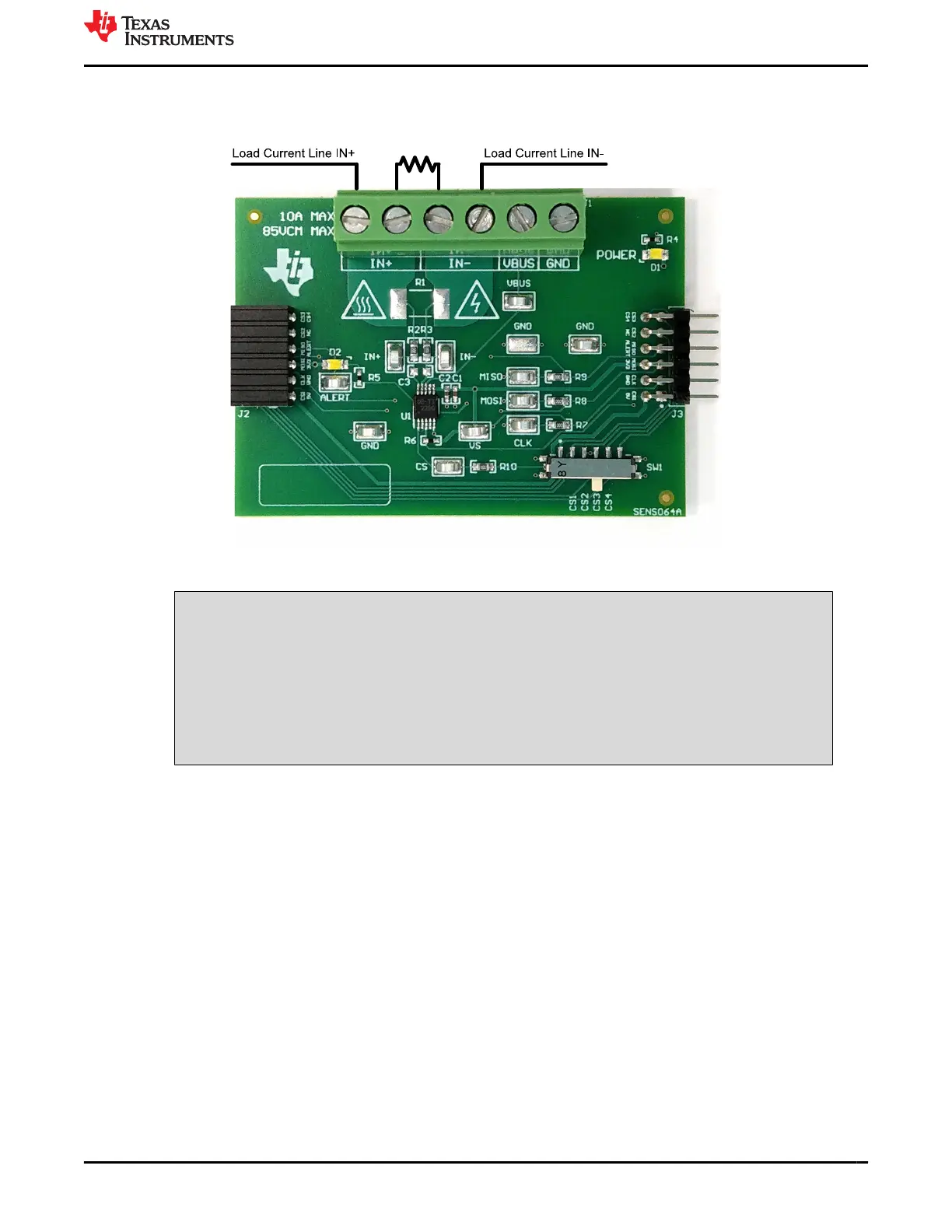
through the EVM. Figure 4-15 shows a convenient way to use the multiple IN+ and IN- terminals with an
external shunt for this use case.
Figure 4-15. IN+ and IN– Wiring for 10A or Less
WARNING
When measuring current, first make sure that the equipment (shunt resistor, wires,
connectors, and so on) can support the amperage and power dissipation. Secondly, make
sure that the current flowing through J1 does not exceed 10 A. Failure to do so can result in
damage to the EVM, or personal injury.
Do not touch high voltage terminals.
The EVM may get hot.
3. Connect the VBUS terminal (J1 pin 2) to the desired bus voltage (likely either IN+ or IN–).
a. If VBUS and dependent features are not being used, this channel can be used as an ADC input for
another voltage.
4. Connect the system ground to the GND terminal (J1 pin 1).
5. Power on the system, and observe the device states and outputs through the GUI.
www.ti.com Operation
SBOU241C – APRIL 2020 – REVISED JULY 2021
Submit Document Feedback
INA228, INA229, INA237, INA238, and INA239 EVM User’s Guide 17
Copyright © 2021 Texas Instruments Incorporated

 Loading...


