4 Current Loop Filter Configuration
Note that if the phase detector frequency is changed significantly, the loop filter needs to be redesigned.
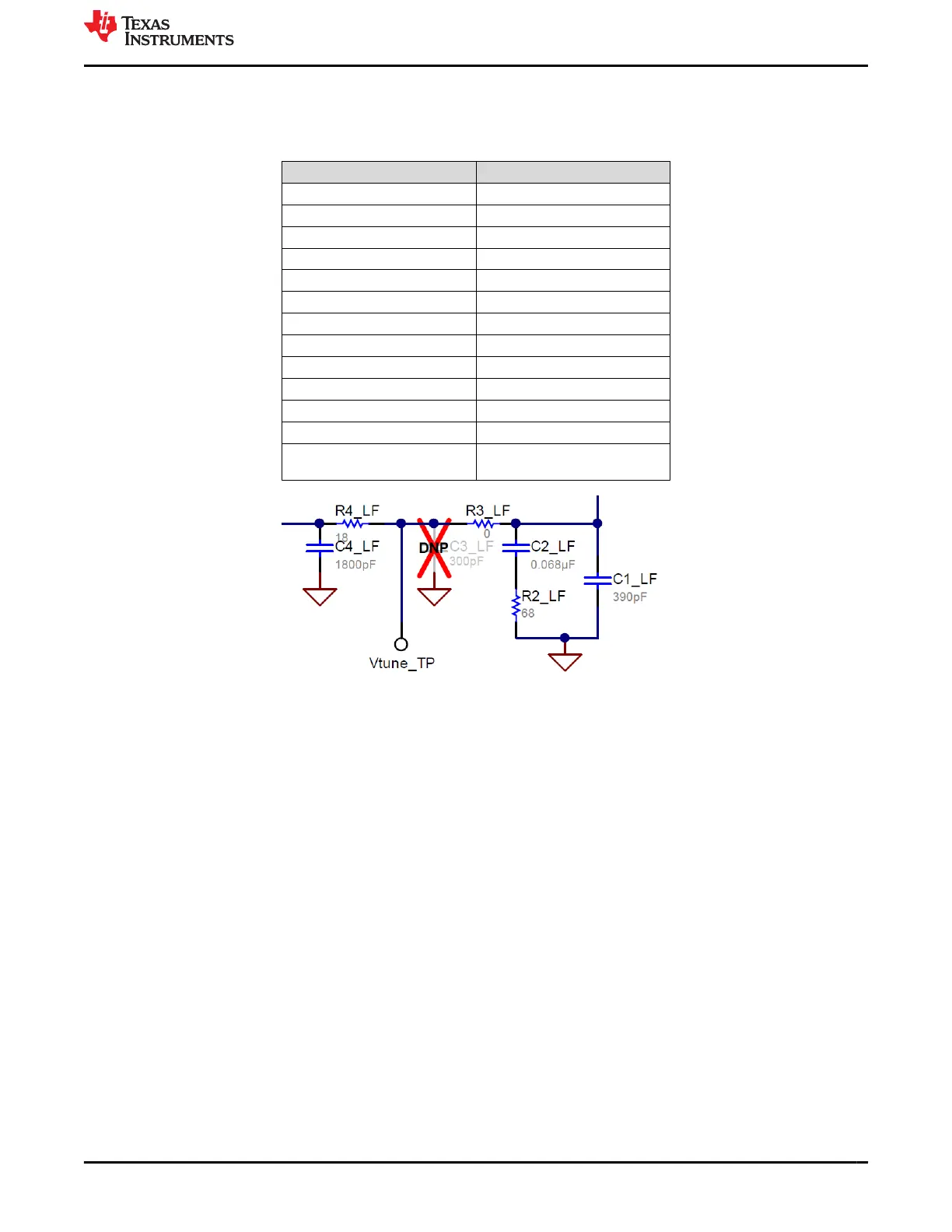
Table 4-1. Current Loop Filter Configuration
PARAMETER VALUE
VCO Gain 132 MHz/V
Loop Bandwidth 285 kHz
Phase Margin 65 deg
C1_LF 390 pF
C2_LF 68 nF
C3_LF Open
C4_LF 1800 pF
R2 68 Ω
R3_LF 0 Ω
R4_LF 18 Ω
Effective Charge Pump Gain 15 mA
Phase Detector Frequency (MHz) 200 MHz
VCO Frequency
Designed for 15 GHz, but works
over the whole frequency range
Figure 4-1. Current Loop Filter Configuration
For detailed design and simulation, see the PLLatinum Sim Tool.
For application notes, videos, and other technical information on TI products, see http://www.ti.com/pll.
www.ti.com Current Loop Filter Configuration
SNAU218A – NOVEMBER 2018 – REVISED AUGUST 2022
Submit Document Feedback
LMX2615EVM-CVAL Wideband 15-GHz Synthesizer 5
Copyright © 2022 Texas Instruments Incorporated