www.ti.com
DDR2 Memory Controller Registers
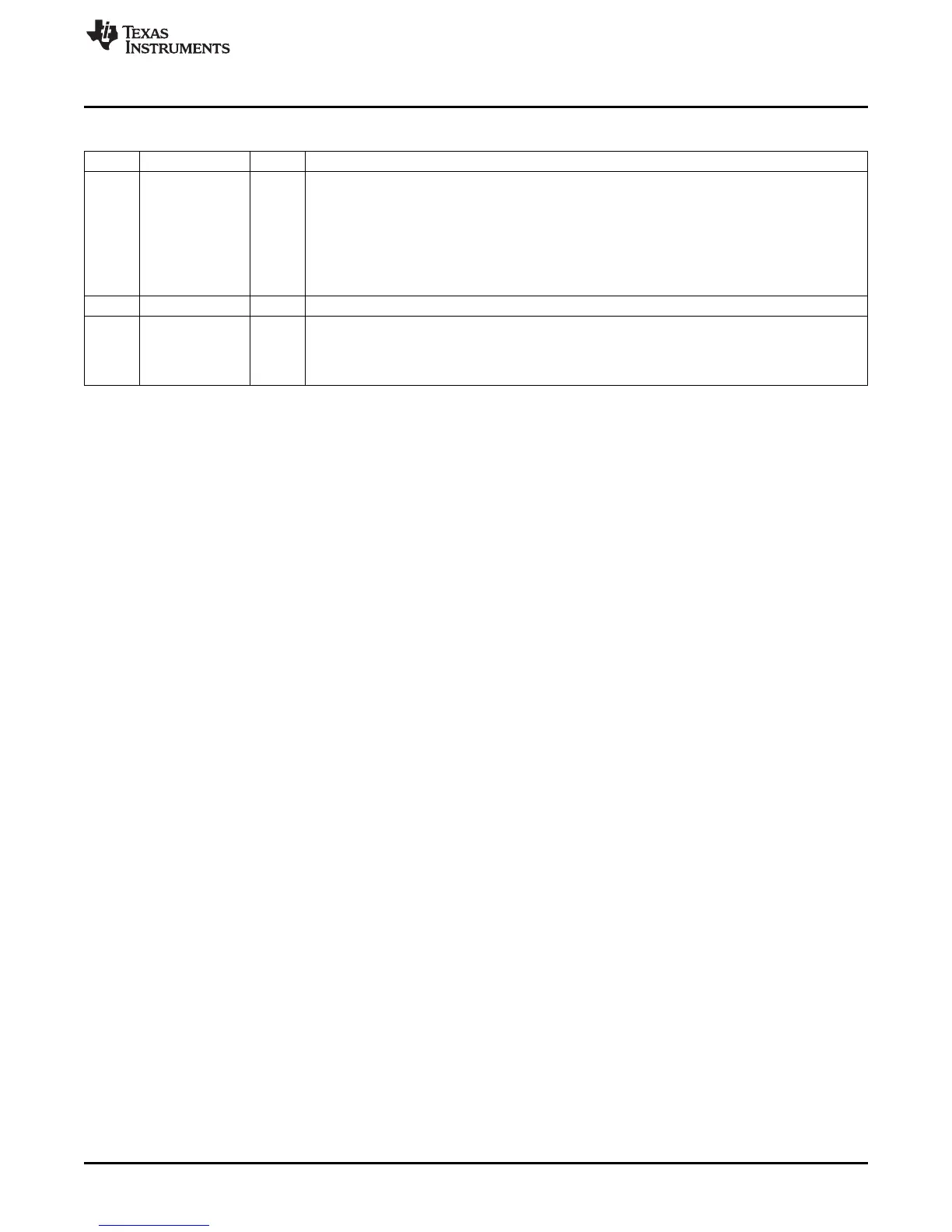
Table 22. SDRAM Timing 1 Register (SDTIM1) Field Descriptions (continued)
Bit Field Value Description
5-3 T_RRD These bits specify the minimum number of DDR2CLKOUT cycles from an activate command to an
activate command in a different bank, minus 1. The value for these bits can be derived from the t
rrd
AC timing parameter in the DDR2 memory section of the device-specific data manual. Calculate
using this formula:
T_RRD = (t
rrd
/DDR2CLKOUT) - 1
When connecting to an 8-bank DDR2 SDRAM, this field must be equal to:
T_RRD = ((4*t
rrd
+ 2*t
ck
) / (4*t
ck
)) - 1
2 Reserved Reserved. The reserved bit location is always read as 0. A value written to this field has no effect.
1-0 T_WTR These bits specify the minimum number of DDR2CLKOUT cycles from the last write to a read
command, minus 1. The value for these bits can be derived from the t
wtr
AC timing parameter in the
DDR2 memory section of the device-specific data manual. Calculate using this formula:
T_WTR = (t
wtr
/DDR2CLKOUT) - 1
45
SPRU970G– December 2005– Revised June 2011 C6455/C6454 DDR2 Memory Controller
Submit Documentation Feedback
Copyright © 2005–2011, Texas Instruments Incorporated

 Loading...