SDRAM
CAN1
ETM
SPI/ADC
JTAG
POR
RST
PWR
USB
EMU
EXP Conn1
SPI2
SD
Slot
XDS100V2
CPLD
FTDI
2332
Ext JTAG
EMIF/
ETM/
SPI2
ENET
RJ45
ENET
PHY
MII/
RMII
CAN
PHY
EXP Conn2
EXP Conn3
Pinmux
DIP
PIN MUX
TMS570LC4357
300 MHz
PIN MUX
CAN/
FRAY/LIN/
GIO/HET
Light
Sensor
Temp
Sensor
CAN2
CAN
PHY
GIO
Button
3.3V/5V A/D 3.3V I/O
1.2V Core
HDK Board Block Diagram
www.ti.com
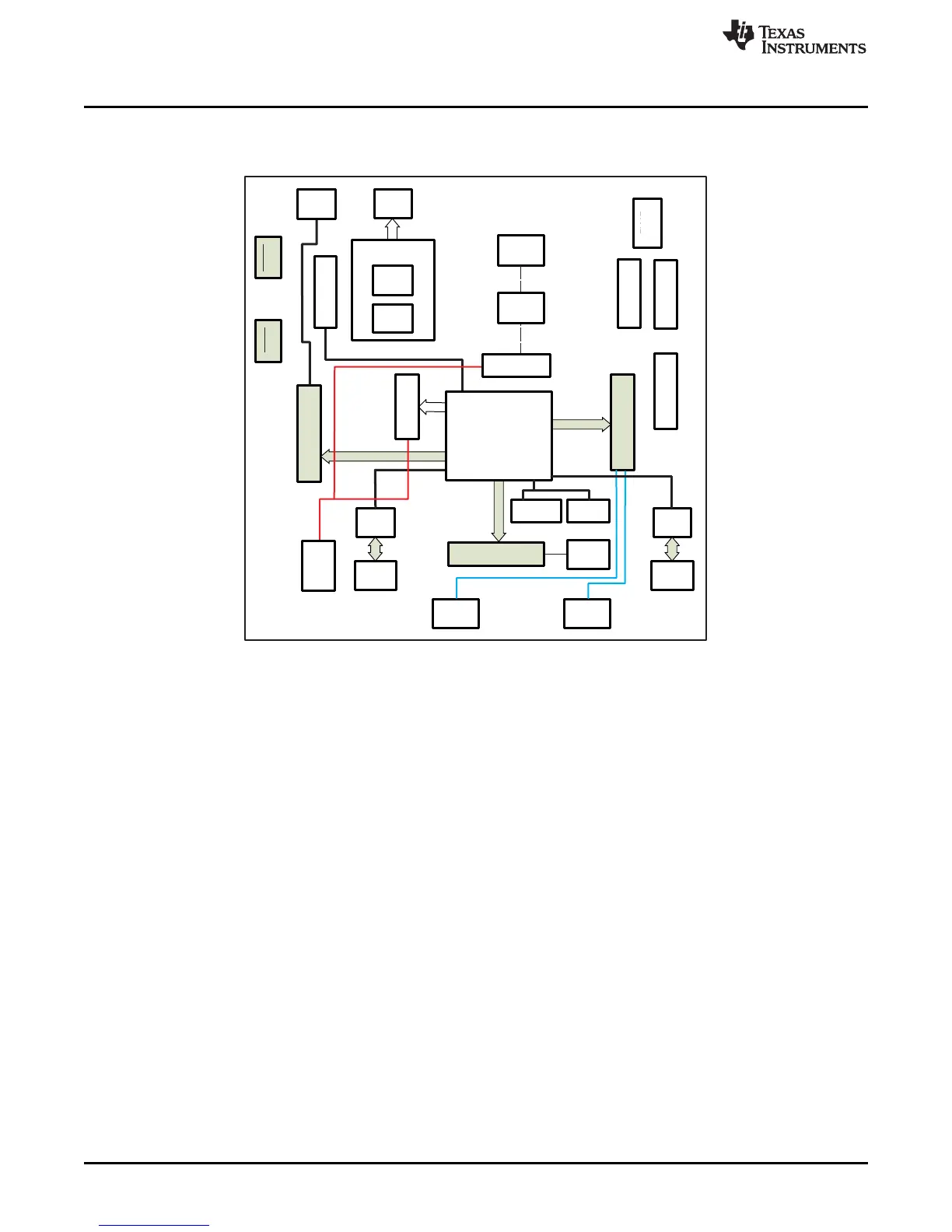
1.3 HDK Board Block Diagram
Figure 1-1 illustrates the HDK block diagram.
Figure 1-1. TMS570LC43 HDK Board Block Diagram
1.4 TMS570LC43 HDK Contents
The kit contains everything needed to develop and run applications for TMS570LC4357 microcontrollers
including:
• Board:
– TMS570LC43 Card
• Cables and Accessories
– 12 V power supply with power adapters for US, or Europe
– Type A to mini B USB cable for using on board XDS100V2 JTAG emulator
– Ethernet cable
– Flashlight for light sensor demo
• CCS DVD Containing:
– Texas Instruments’ Code Composer Studio™ Integrated Development Environments (IDE)
• Hercules DVD Containing:
– Hercules Safety Demos
– Hardware Abstraction Layer Code Generator (HALCoGen)
– Training Videos
– Device Documentation
6
Introduction SPNU597–May 2014
Submit Documentation Feedback
Copyright © 2014, Texas Instruments Incorporated