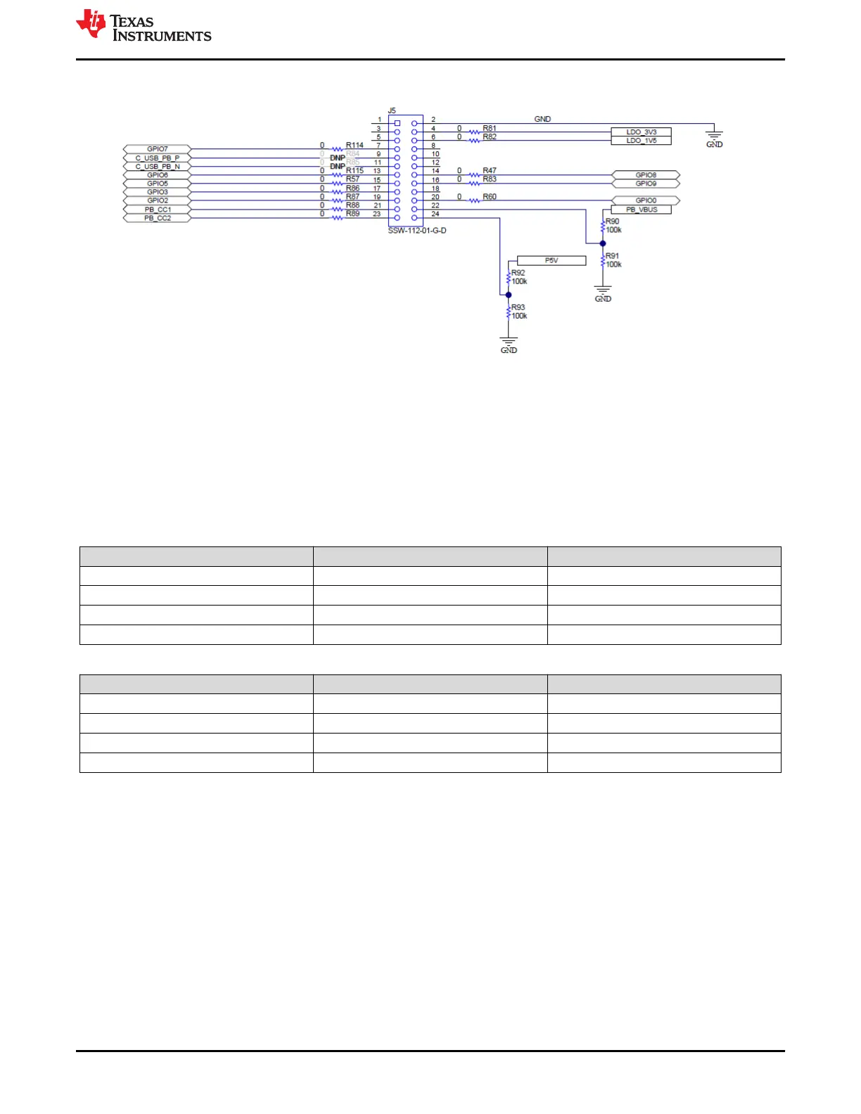
Figure 4-9. Debug Header (J5) Schematic
4.2 LED Indicators Description
The EVM has multiple LEDs to notify the user what type of connection is present. The LEDs are separated into 2
groups: MUX control LEDS and Status LEDs. All LEDs are enabled with general purpose I/O (GPIO); therefore,
each must be enabled separately via configuration, if configuring a custom image
4.2.1 MUX Control LEDs
Table 4-2. Port A MUX CTL LED
LED Indicator GPIO Function
D15 - PA_HPD GPIO1 HPD
D17 - PA_USB3 GPIO3 USB 3.0 Event
D18 - PA_DP_Mode GPIO4 DP Mode Select Event
D23 - PA_POL GPIO9 Cable Orientation Event
Table 4-3. Port B MUX CTL LED
LED Indicator GPIO Function
D14 - PB_HPD GPIO0 HPD
D19 - PB_USB3 GPIO5 USB 3.0 Event
D22 - PB_DP_Mode GPIO8 DP Mode Select Event
D16 - PB_POL GPIO2 Cable Orientation Event
4.2.2 Status LEDs
D1 and D2 LEDs indicate when VBUS voltage is present on port A and port B respectively. They also provide a
voltage discharge path for high to low PD contracts. D4 LED indicates SYS_PWR, when a barrel jack is
connected at J2.
www.ti.com
Setup
SLVUBM1C – JANUARY 2019 – REVISED JANUARY 2021
Submit Document Feedback
TPS65994 EVM User Guide 9
Copyright © 2021 Texas Instruments Incorporated