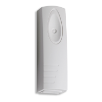
INS877-4 10/26
Icon Item
A LED function select DIP switch
B Sensitivity selection button
C Alarm resistance value selection DIP switch
D Tamper resistance value selection DIP switch
E Input terminal block
F Removal from mounting breakout
2.0 Mounting
2.1 Device mounting
Select the intended mounting position. The device can be installed in any
mounting orientation.
Open the device cover and remove the PCB using a screwdriver (see figure 1)
Remove the cable knockouts (see figure 2)
To ensure product compliance with EN50131, fix the base onto the
mounting surface (see figure 3) using the following screw type:
Head Type: Counter Sunk flat head
Head Diameter: 5.3-6.8mm
Screw Diameter 2.9-3.2mm
Screw length: 15.8-24.5mm
Impaq S Grade 3 MUST use the fixing points shown in RED on Fig 3 for the
removal from mounting tamper to function correctly.
Care should be taken when screwing through the PCB for the rear
tamper breakout. Overtightening the screw could cause the PCB tracks
to break and leave the device permanently in tamper. This is not
reversible and the PCB will need to be replaced.
NOTE 1: If the product is mounted on concrete, suitable wall plugs should be used.
NOTE 2: If installing the Impaq SC the same screw types should be used to mount

 Loading...