INS877-4 20/26
NOTE: The product will only function if both DIP switches have a single switch set
to the ON position. If multiple switches are moved, the product will not function as
expected.
Optional wiring
There is a facility to remotely enable the walk test LED from the panel. To use this
connect a wire from the RLED terminal to an output of the panel.
NOTE: This overrides the LED DIP Switch settings.
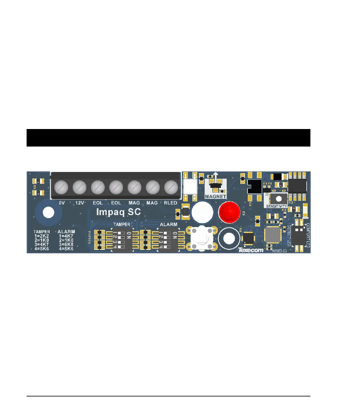
4.0 Impaq SC wiring configuration
The Impaq SC has only one wiring option
The Impaq SC’s only wiring option is EOL via DIP switches. The zone wires should
be connected to the EOL terminals, and the required EOL resistor options should
be chosen on the EOL DIP switches.
Connect two cores into the terminals marked MAG for the alarm signals from the
magnetic contact.
Note: The shock and contact functions must be wired as two separate zones in the
panel.
 Loading...