OPERATION AND SERVICE INFORMATION
Page 2
Owner’s Manual and Service Guide
Read all of Manual to become thoroughly familiar with this vehicle. Pay particular attention to all Notes, Cautions and Warnings
operational with the key switch in the ‘OFF’ position.
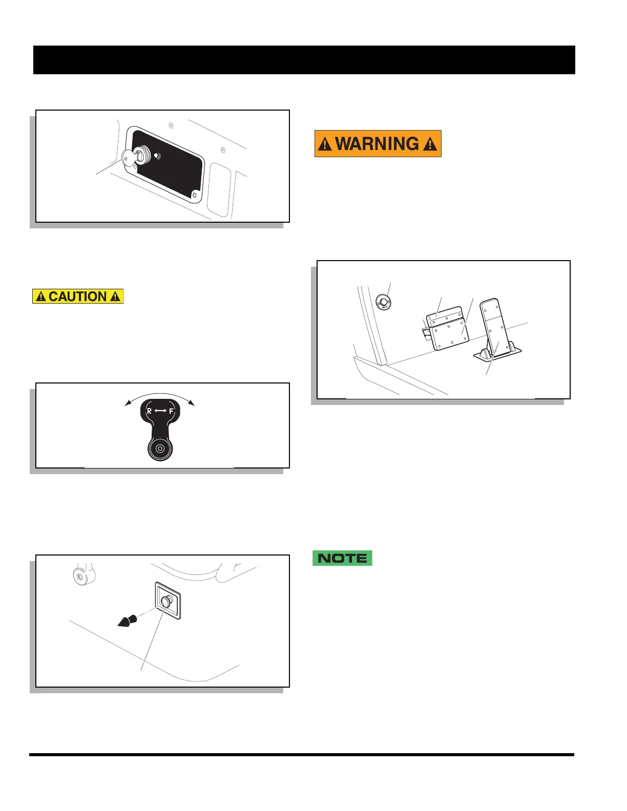
DIRECTION SELECTOR
To reduce the possibility of com-
ponent damage, the vehicle
must be completely stopped before moving the
direction selector.
Located on the seat support panel, this lever permits the
selection of either ‘F’ (forward) or ‘R’ (reverse) (Ref Fig. 3
on page 2). Vehicle should be left in ‘F’ when unattended.
CHOKE
The choke is used to aid cold starting (Ref. Fig. 4 on
page 2). See COLD STARTING section for operating
instructions.
ACCELERATOR PEDAL
Unintentional move-
ment of the acceler-
ator pedal will
release the park brake and may cause the
vehicle to move which could result in
severe injury or death.
With the key switch ‘ON’, depressing the accelerator
pedal starts the engine. When the pedal is released, the
engine will stop (Ref Fig. 5 on page 2). To stop the vehi-
cle more quickly, depress the service brake.
If key switch is ‘ON’ and park brake is set, depressing the
accelerator inadvertently will release the park brake and
will cause the vehicle to move which could cause severe
injury or death.
Depressing the accelerator pedal will release the park
brake if it is engaged. This is a feature to assure the vehi-
cle is not driven with the park brake engaged. Depress-
ing the accelerator pedal is not the preferred method of
releasing the park brake.
Depressing the lower section of the brake
pedal is the preferred method of releasing the
park brake to assure the longest service life of brake compo-
nents.
COMBINATION SERVICE AND PARK BRAKE
PEDAL
The brake pedal incorporates a park brake feature (Ref
Fig. 5 on page 2). To engage, push down on the upper
section of the pedal until it locks in place. The park brake
will release when the service brake pedal is depressed.
Use the lower section of the brake pedal to operate the
service brake system.
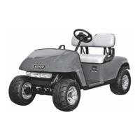
Fig. 2 Key / Light Switch
Fig. 3 Direction Selector
Fig. 4 Choke
OFF
ON
ef Kes 11
Key/Light Switch
Forward
Reverse
Ref Dsl 2
Choke
Ref Chk 1
Fig. 5 Accelerator, Brake and Horn Controls
Park
Brake
Accelerator
PARK
Service
Brake
Ref Abc 1
Horn