C-5
SELECTOR VALVE appendix C-5
OPTIONAL SELECTOR VALVE INSTALLATION INSTRUCTIONS
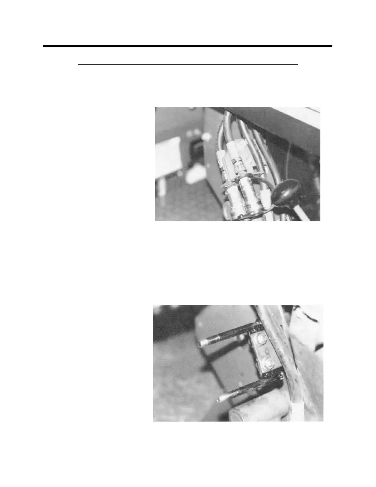
1. Re move 5/16 x 3/4 flange bolts
hold ing the aux il iary hy drau lic
quick con nec tors. Re move
quick cou plings and hoses
from brack ets.
(See Photo C--7)
2. Us ing the 5/16 flange bolts re -
moved in step 1, bolt the se -
lec tor valve mount ing bracket
to the tab that held the quick
con nec tors. Place the bracket
on the rear side of the tab.
(See Photo C--8)
Photo C-7
Photo C-8