©Copyright Task Force Tips LLC 2008-2021 11 LIY-300 January 13, 2021 Rev18
4.0 INSTALLATION
4.1 ELECTRICAL INSTALLATION
See Remote Control (RC) Monitor Electrical Controls Supplemental Instructions LIY-500.
4.2 STRUCTURAL REQUIREMENTS
The structure that the monitor is mounted to must withstand the internal
pressure of the monitor as well as shear and bending forces due to nozzle
reaction.
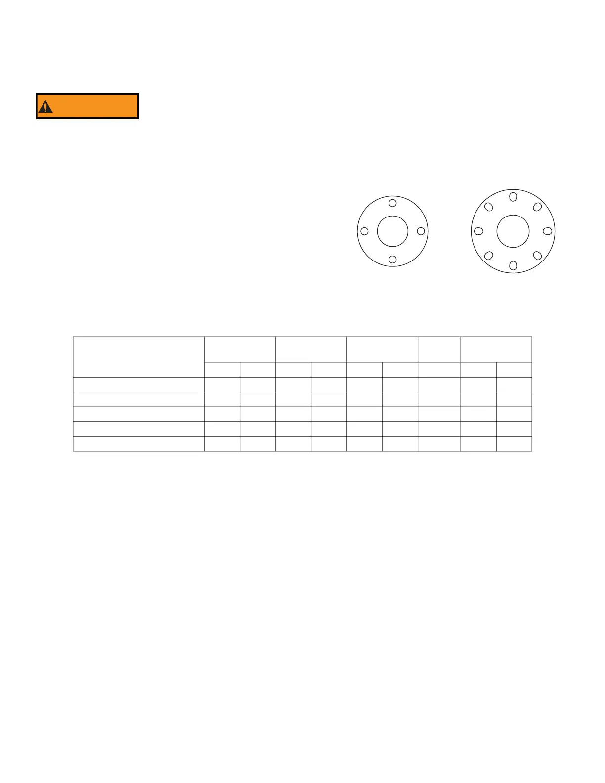
For flanged connections, the use of flat flanges without raised faces is
recommended. Use a ring gasket as defined in ASME 16.21 or ISO 7483.
Tighten flange bolts in an alternating sequence as shown below. Tighten
sequentially each bolt or stud three times to 30%, then 60%, and finally
100% of the specified torque. Tighten to a total of 76-80 ft-lb (100-110 N·m).
Table 4.2
Reaction forces generated by master stream flows are capable of causing injury and property
damage if not properly supported. Monitors should be securely installed by qualified individuals.
• Mounting objects must be capable of withstanding maximum nozzle reaction force listed in
SPECIFICATIONS.
• The monitor must be securely mounted to rigid support members.
• Do not use flanges or pipe made from plastic for monitor mounting.
• Torque all fasteners to specified values.
FLANGE TYPE OUTSIDE
DIAMETER
THICKNESS BOLT HOLE
CIRCLE
# OF
BOLTS
SIZE OF
BOLTS
in mm in mm in mm in mm
2.5” ANSI 150 6.9 175 0.98 25 5.5 140 4 5/8 16
3” ANSI 125/150-DN80 PN20 7.5 190 0.75 20 6.0 152.5 4 5/8 16
4” ANSI 150-DN100 PN20 9.0 230 0.94 23 7.5 190 8 5/8 16
DN80, PN16 Flange 7.9 200 0.87 22 6.3 160 8 5/8 16
DN100, PN16 Flange 8.7 220 0.87 22 7.1 180 8 5/8 16
1
3
2
4
1
5
3
7
2
6
4
8
Tighten Sequentially Each Bolt Three Times
to a Total of 76-80 ft-lb (100-110 N·m)
Figure 4.2
 Loading...