20
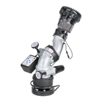
Two versions of the RC monitor have been designed for installation on aerial device trucks, the "-L" and "-P" versions. The "-L"
version is supplied with one cable for connecting discrete inputs into the electronics enclosure, typically connections to a Canbus
output module or toggle switches located at the turntable. The "-P" version is supplied with two cables for connecting discrete
inputs, one cable typically for controls located in the basket and one cable for controls located at the turntable.
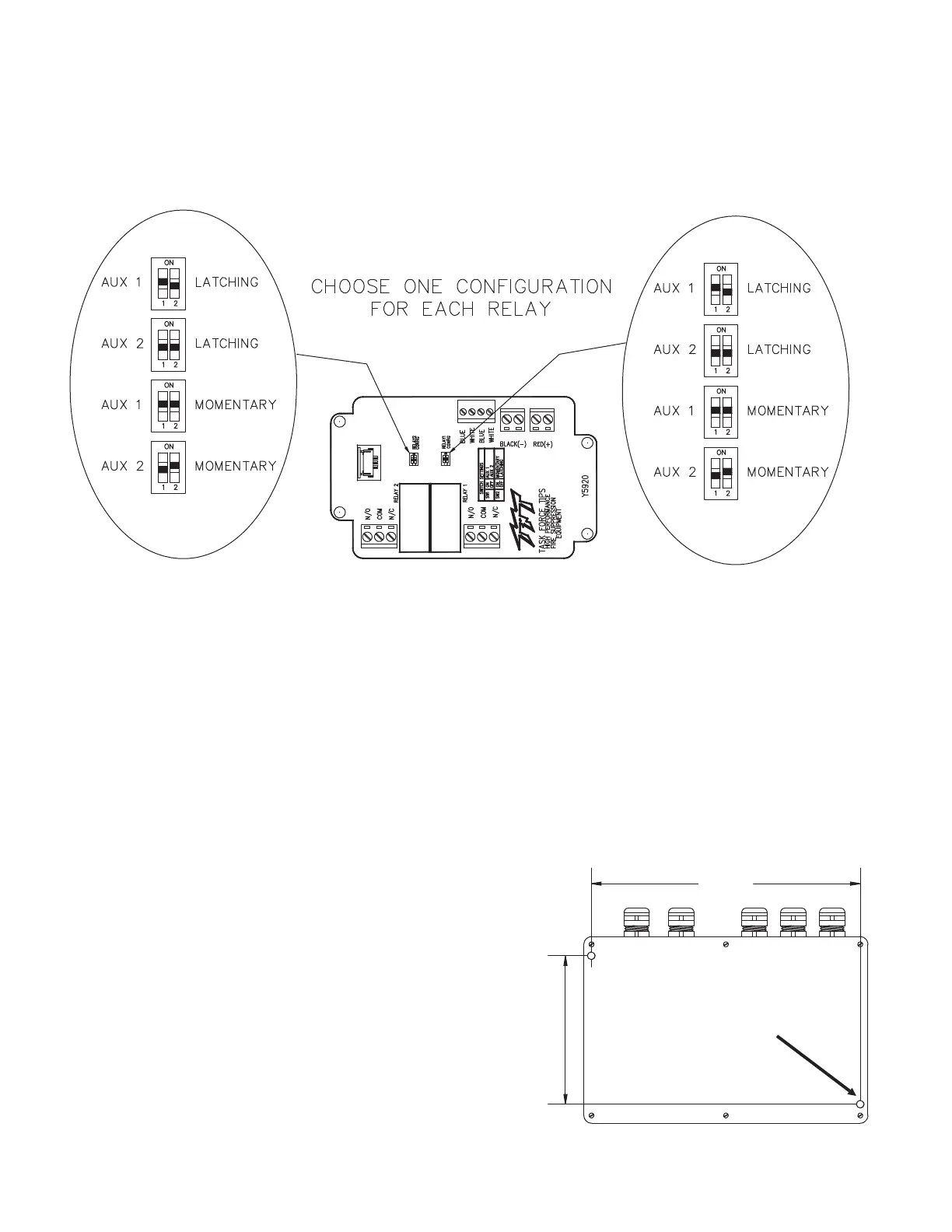
5.10.1 ELECTRONICS ENCLOSURE MOUNTING
Select proper enclosure location. Enclosure is designed to be surface
mounted and the size is 5 3/4” x 8 3/4” (146 x 222mm). Height of
enclosure is 2 1/4” (57mm). Refer to Figure 5.10.1 for mounting hole
dimensions.
Fig 5.10.1
Electrical Enclosure Mounting Hole Dimensions
MOUNT ENCLOSURE WITH
(2) 1/4-20 FASTENERS
TIGHTEN SECURELY
4.56
(116 mm)
8.25
(210 mm)
5.10.2 ELECTRICAL WIRING
On aerial devices, the installer will supply the required cables that run
up the ladder or boom. Be sure to perform voltage drop calculations to
verify that the supply voltage will remain at an acceptable level during
monitor operation.
5.8.3 CONFIGURATION
5.10 ELECTRICAL RC MONITOR AERIAL TRUCK INSTALLATION
The two relays on the circuit board can be individually configured as AUX1 or AUX2. Also the actuation of each relay can be configured
to be momentary or latched. See Figure 5.9.3 for relay configuration DIP switch settings.
Remove lid from interface box.
Locate DIP switches on board and select configuration.
Replace lid. Verify rubber seal is clean and undamaged. Verify that no wires are caught between lid and box.
1.
2.
3.
Figure 5.8.3
Relay Configuration
5.9 CONNECTING MONITOR CABLE DIRECTLY TO PROTECTED POWER SUPPLY
The electric RC monitor has an operator station, which is fully functional, mounted on the monitor. If no other operator stations are
selected, with the exception of the wireless radio remote, the installer will only need to connect power to complete the installation. Route
cable from monitor and connect to a protected circuit from the truck’s power distribution center. Connect the red wire to positive and the
black wire to negative (ground). Cut and discard blue and white wires.