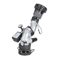
4.3 NOZZLE INSTALLATION
The nozzle is simply screwed onto the monitor's exit threads.
For nozzles with electric pattern control, a cable with a female, waterproof connector is provided at the outlet of the Tornado RC which
attaches directly to several of TFT's electric nozzles. The cable used is a dual-key, micro type plug assembly. Any other nozzle should
have the corresponding male electrical connector installed. The waterproof cap should be installed when using stacked tips. Do not cut
off the female connector on the monitor. This connector is molded onto the cable and must remain in place to maintain the water
tightness of the electrical system.
CAUTION
The nozzle threads must match the threads of the Tornado monitor in both size and type.
Mismatched or damaged threads may cause the nozzle to leak or uncouple under pressure and
could cause injury.
CAUTION
Do not connect aluminum to brass or brass to aluminum. Dissimilar metals coupled together can
cause galvanic corrosion that will freeze the threaded joint or cause complete loss of thread
engagement. If dissimilar metals must be coupled together, the effects of corrosion can be greatly
delayed by various coatings on the metal such as powder paint, hard anodizing, or silicone grease.
4.4 PRESSURE GAGE PORT
There is a raised boss on the back of the monitor. This raised boss is not machined from the factory but may be drilled and tapped for ¼
NPT threads if a pressure gage is desired on the monitor.
9
4.5 DRAIN
There is no drain on the Tornado Monitor itself.Adrain valve should be installed on the monitor's inlet piping.
11/32” nut driver
20mm open-end box wrench
17mm open-end box wrench
5/32” drill bit
25/32” drill bit
#2 Phillips screwdriver
Small flat blade screwdriver
Wire cutter/stripper
Terminal crimping tool
Utility knife
Recommended Tool List
IMPORTANT - When mechanical installation and electrical connections are complete, perform the following test to verify voltage
supply is adequate and the current limiting feature is functioning.
1) Apply power to monitor control box.
2) Press LEFT or RIGHT button and hold until monitor reaches its stop position. Continue to hold button down.
3) Once movement is stopped, manually turn override knob in opposite direction while continuing to hold button down. If knob
can be turned, then voltage supply is adequate. If knob cannot be turned and motor continues to operate, then the voltage
supply or wiring is not adequate. Check connections and voltage connection point, rewire if necessary. NOTE: Override
knob will only turn in one direction.
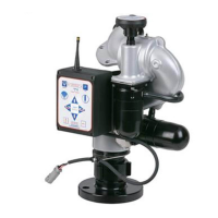
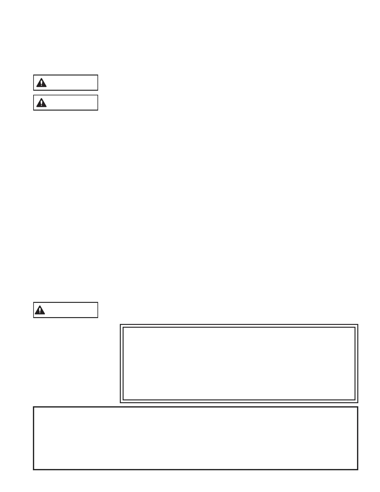
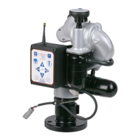
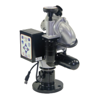
5.0 ELECTRICAL CONTROLS INSTALLATION
The electric RC monitor is supplied with a monitor mounted operator station. The wiring on the monitor and for this operator station is
factory installed. The assembly is supplied with a 30-foot length of cable for connection to the operator control stations as shown in
Figure 5.0 or directly to a protected voltage supply. This cable has 4-conductors which supply power and the communications from the
operator stations to the monitor. To complete the installation, the installer will need to mount and wire the selected operator stations. The
power supply for the monitor will need to be connected to a protected circuit from the truck's power distribution center. Refer to the
specifications section 3.2.1 for nominal current draw.
For installations where the customer would like to turn off the voltage to the monitor independent of the truck master switch, the installer
needs to install a SPST (single-pole single-throw) toggle switch. Install this toggle switch in a location that can quickly be accessed
before using the RC monitor. The toggle switch needs to be wired between the protected voltage supply and the red wire feeding the RC
monitor.
Good mechanical connections on the wires are absolutely necessary and should be checked periodically. Poor electrical
connections can cause power loss to the electric RC monitor and be a fire hazard.
Careful selection of wiring is critical to avoid excessive voltage drop.
Be careful to route cables in a protected area away from high heat sources.
Use grommets whenever wires pass through holes to prevent damage due to snags, abrasions, etc.
Secure cables close to control box with plastic wire ties or cable clamps to relieve stress on the cables.
Disconnect power before installing or servicing the electrical components. The RC monitor control boxes and motors are not rated
as ignition proof, explosion proof, or intrinsically safe.
!
!
!
!
!
!
The electric motors and other components are ignition sources. The electric drives should be
operated only in areas where there is adequate ventilation and no hazard of flammable vapor
buildup.
WARNING
6.2.1 OPERATOR STATIONS
6.2.1.1 MONITOR MOUNTED OPERATOR STATION
6.2.1.2 PANEL MOUNT OPERATOR STATION (Y4E-RP)
6.2.1.3 TETHER OPERATOR STATION (Y4E-CT-##)
6.2.1.4 WIRELESS OPERATOR STATION (YE-RF-##)
6.2.1.5 JOYSTICK OPERATOR STATION (Y4E-JS)
6.2.1.6 TOGGLE SWITCH OPERATOR STATION (Y4E-TS)
IMPORTANT
Review these sections and decide on locations before starting
installation process.