17
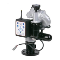
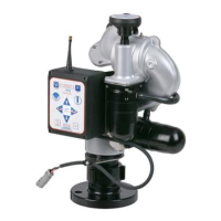
5.5 TOGGLE SWITCH MONITOR OPERATOR STATION (Y4E-TS)
This operator station allows the monitor to be controlled by three toggle switches. The installer will need to mount the operator station
and connect the cable to the monitor and power.
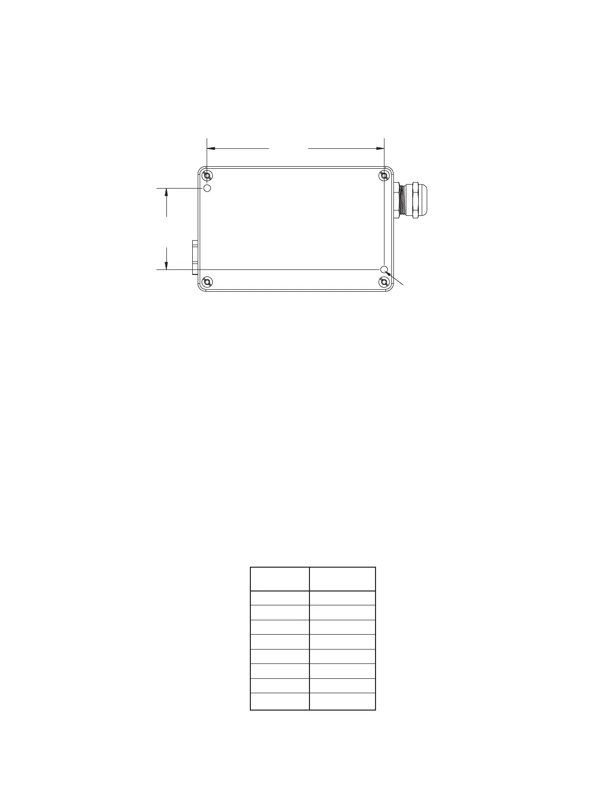
5.5.1 ENCLOSURE MOUNTING
Select proper operator location. Enclosure is designed to be surface mounted and the size is 5” x 3 1/8” (127 x 80mm). Height to top of
switches is 3 1/8” (80mm). Refer to Figure 5.5.1 for mounting hole dimensions.
4.45
(113 mm)
2.05
(52 mm)
Figure 5.5.1
Toggle Switch Operator Station Hole Dimensions
5.5.2 ELECTRICAL WIRING
See figure 5.0 for typical connections. The 4-conductor cable from the operator station needs to be connected to power (red & black)
and to the communication link (blue & white) from the monitor. Refer to Figure 5.1.2 for typical cable preparation
MOUNT ENCLOSURE
WITH (2) 1/4-20 FASTENERS.
TIGHTEN SECURELY.
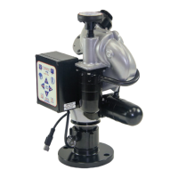
5.6 COMMUNICATION INTERFACE BOX (Y4E-COMM)
This Communication Interface Box converts discrete input signals into serial communications for controlling the monitor. The discrete
input signals can be from a joystick, toggle switches, relay contacts or Canbus output module. The interface box accepts +12/24 VDC
signals, but can be field changed to accept ground signals. The installer will need to mount the interface box and connect the cable to the
monitor and power.
5.6.1 ENCLOSURE MOUNTING
Select proper enclosure location. Enclosure is designed to be surface mounted and the size is 5” x 3 1/8” (127 x 80mm). Height of
enclosure is 2 3/8” (60mm). Refer to Figure 5.5.1 for mounting hole dimensions.
5.6.2 ELECTRICAL WIRING
See figure 5.0 for typical connections. The 4-conductor cable from the communication interface box needs to be connected to power
(red & black) and to the communication link (blue & white) from the monitor. Refer to Figure 5.1.2 for typical cable preparation.
See figure 5.6.2 for connecting INPUTS cable.
UP
DOWN
LEFT
RIGHT
FOG
STREAM
(-) BLACK
(+) RED
WHITE
BLUE
YELLOW
BROWN
GREEN
ORANGE
BLACK
RED
Function
Interface Box
Cable Color
Figure 5.6.2
Communication Interface
Wire Color/Function