Audio Codec Adapter Setup for Cinterion
®
Modules
2.2 NAU8822 Audio Codec Adapter
33
audio_codec_adapter_setup_v04 2019-10-16
Confidential / Released
Page 12 of 34
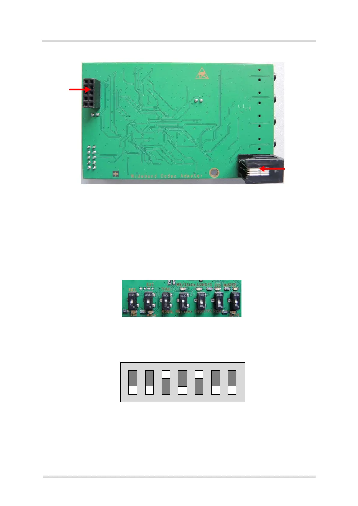
Figure 7: Audio Codec Adapter bottom view
Note: Only one out of Handset and Headset interface can be connected and operated at a time.
2.2.1.1 DIP Switch Default Settings
The following figure shows the default settings for the DIP switch. These settings configure a
basic slave mode that should straightforwardly work with most Cinterion
®
modules. For more
information on how to set the DIP switch see Section 3.1.1.4.
Figure 8: DIP switch defaults (e.g., ELS61-ER2)
Bottom
Digital
Handset
plug (RJ9)
Audio
Interface
(DAI)
Slave(SLV)
PCM
SHORTFS
NB/8kHz
TC65i(1.8V)
MCKL(int.)
I2C(int.)
Master(MST)
I2S
LONGFS
WB/16kHz
Norm.(3.0V)
EXT.(MCLK)
EXT.(I2C)