Audio Codec Adapter Setup for Cinterion
®
Modules
3.1 Assembly with DSB75 and AH6-DSB75 Adapter
33
audio_codec_adapter_setup_v04 2019-10-16
Confidential / Released
Page 19 of 34
3.1.1.4 DIP Switch and AT Command Settings
MAX9860
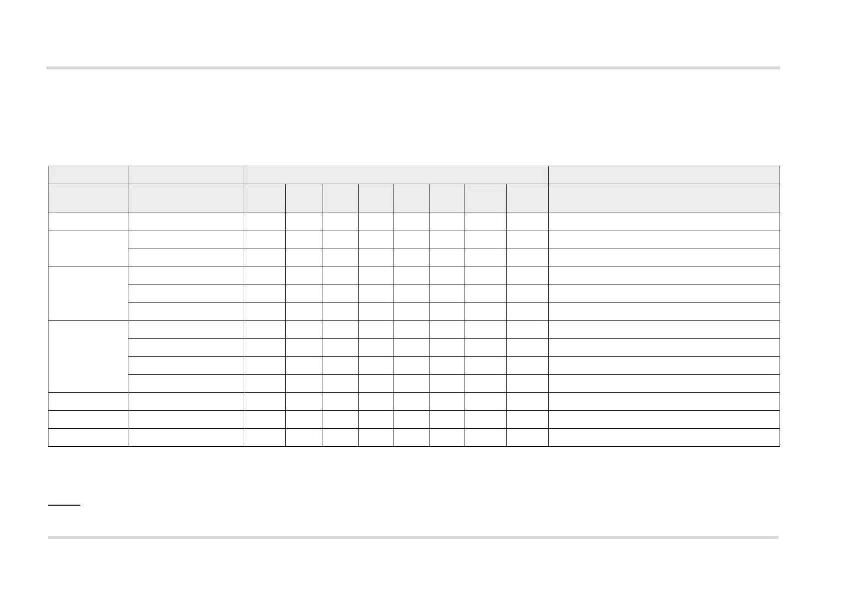
Table 4 list the default DIP switch and AT^SAIC command settings required to setup the MAX9860 for a specific (sample) module.
Legend:
0: Switch set to the left position; 1: Switch set to right position; X: Switch setting irrelevant
"LEDs": The colors
, , and indicate the color of the LEDs that light up at the Audio Codec Adapter.
Table 3: MAX9860 DIP switch and AT command settings for selected products
Product AT^SAIC setting Audio Codec Adapter DIP switch settings Comment
Slave/
Master
MST2/
MST1
PCM/
I2S
Short/
Long
NB/
WB
1.8V/
3.0V
Int./Ext.
MCLK
Int./Ext.
I2C
EHS5/6 - 0 X0 1 0 1 0 0
BGS2/AGS2 SAIC=1,1 0 X0 1 0 1 0 0
SAIC=3,1 0 X1 0 0 1 0 0
PHS8 R3 SAIC=1,1,1,2,0,0,1 0 X0 0 0 1 0 0
SAIC=1,1,1,1,0,0,1 0 X0 0 0 1 0 0
SAIC=1,1,1,2,1,0,1 1 1 0 0 0 1 0 0 Check master setting on the AH6-DSB75 Adapter.
1
1.
The module (configuration) is a slave for clock as well as frame synchronization signals generated on the Audio Codec Adapter. Note: In this case the MS – AGND jumper on
AH6-DSB75 Adapter (X305) must be removed for correct signal directions through the AH6-DSB75 Adapter’s voltage converters. The MS - AGND jumper is show in Figure 11.
PLS8 R3 SAIC=1,1,1,3,0,0,1,0 0 X0 0 0 1 0 0
SAIC=1,1,1,2,1,0,1,1 1 1 0 0 1 1 0 0 Check master setting on the AH6-DSB75 Adapter.
1
SAIC=3,1,1,1,0,0,1,0 0 X1 X0 1 0 0
SAIC=3,1,1,1,0,0,1,1 0 X1 X1 1 0 0
PLS8 R2 SAIC=3,1,1,0,0,0,1,0 0 X1 X01 0 0
ALAS3 SAIC=1,1,1,0,0,0,1,0 0 X0 0 0 0 0 0 DSB75 adapter for ALAS3 requires 1.8V levels.
2
2.
Note: With ALAS3 evaluation modules the ALAS6-DSB75 Adapter is required instead of the AH6-DSB75 Adapter. As this adapter supports 1.8V voltage levels, the correspond-
ing level switch must be set to “1V8”.
ELS31 SAIC=1,1,1,4,1,1,1,1 1 1 0 1 1 1 0 0 Check master setting on the AH6-DSB75 Adapter.
1