Audio Codec Adapter Setup for Cinterion
®
Modules
3.1 Assembly with DSB75 and AH6-DSB75 Adapter
33
audio_codec_adapter_setup_v04 2019-10-16
Confidential / Released
Page 18 of 34
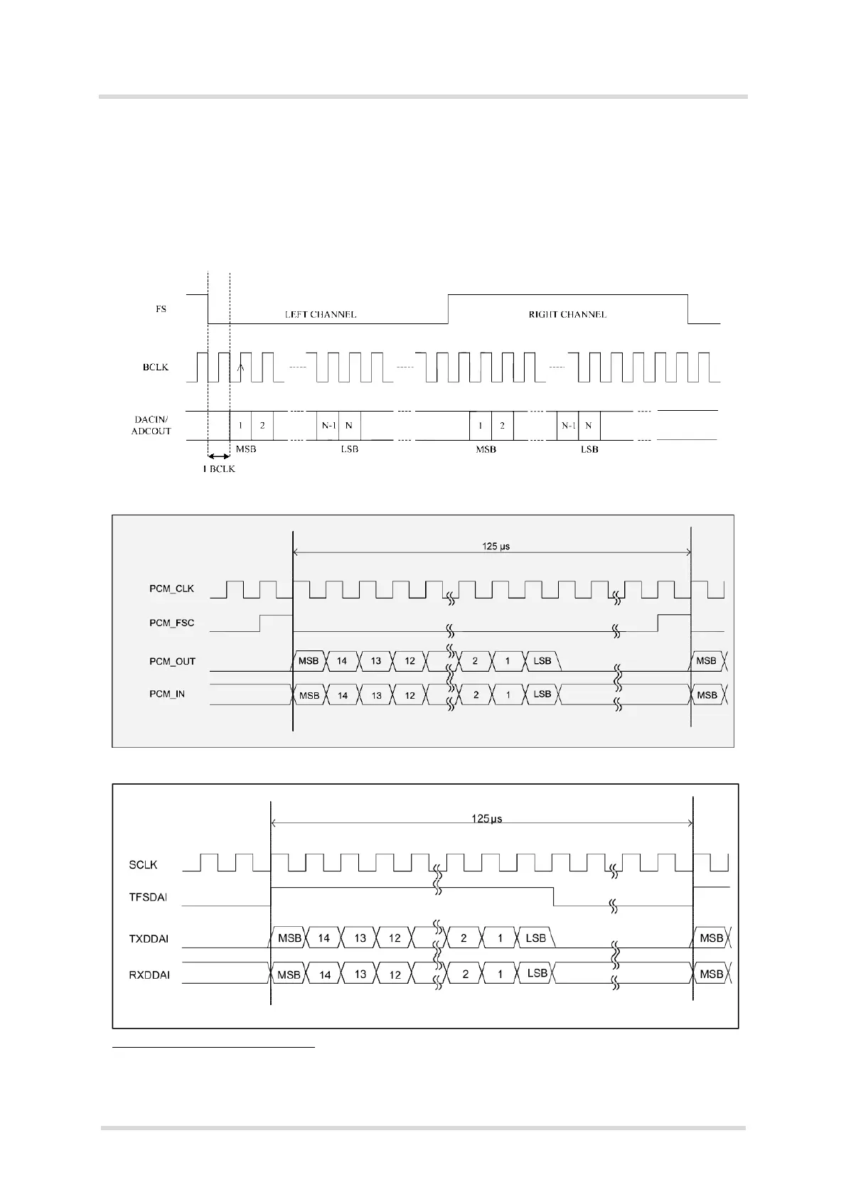
Please note that all PCM data and frame synchronization signals are written to the PCM bus
on the rising clock edge and read on the falling edge, whereas all I2S data and frame synchro-
nization signals are written to the I2S bus on the falling clock edge and read on the rising edge.
The following figures show the various timings for the Framesync modes. For a further mea-
sured sample please also refer to Appendix A - DAI Signal Timings at Oscilloscope.
I2S mode
3
PCM short FSYNC mode (NB)
PCM long FSYNC mode (NB)
3.
Most modules use I2S left channel only. PHS8 can use the right channel for microphone array function-
ality.