Audio Codec Adapter Setup for Cinterion
®
Modules
4 Appendix A - DAI Signal Timings at Oscilloscope
33
audio_codec_adapter_setup_v04 2019-10-16
Confidential / Released
Page 24 of 34
4 Appendix A - DAI Signal Timings at Oscilloscope
DAI signal timings as shown in Section 3.1.1.3 can be visualized using an oscilloscope. The
oscilloscope’s probe heads should be attached to the appropriate signal pads at the Audio Co-
dec Adapter’s top side as shown below in Figure 12 (Din corresponds to a module’s PCM_IN
or RXDDAI signal, Dout to PCM_OUT or TXDDAI, FSC to PCM_FSC or TFSDAI, and BCLK
to PCM_CLK or SCLK).
i
Figure 12: DAI signal lines at (MAX9860) Audio Codec Adapter’s top side
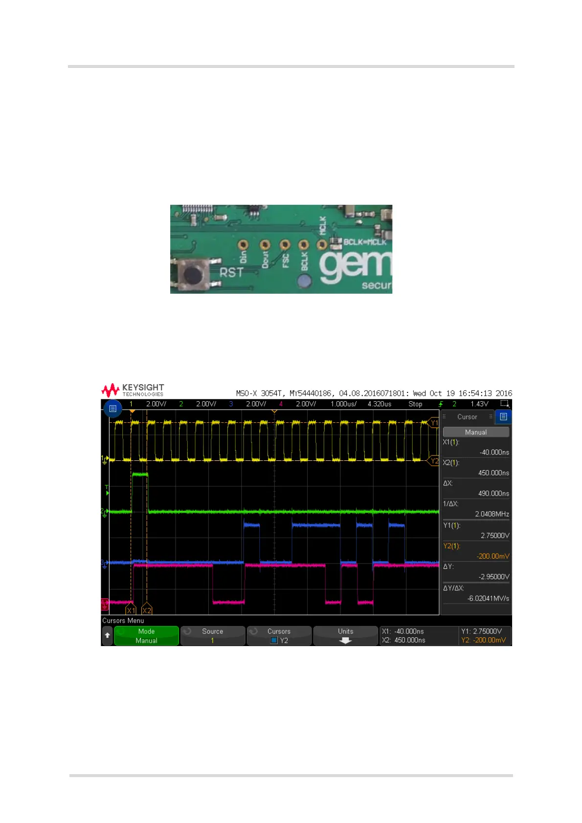
The following figures show sample measurement results for an ELS31 module’s DAI interface
lines. Figure 13 gives a short frame detail, while Figure 14 shows a complete frame. Compare
these to the figures given in Section 3.1.1.3.
Figure 13: Timing sample (details) for DAI signal lines