30
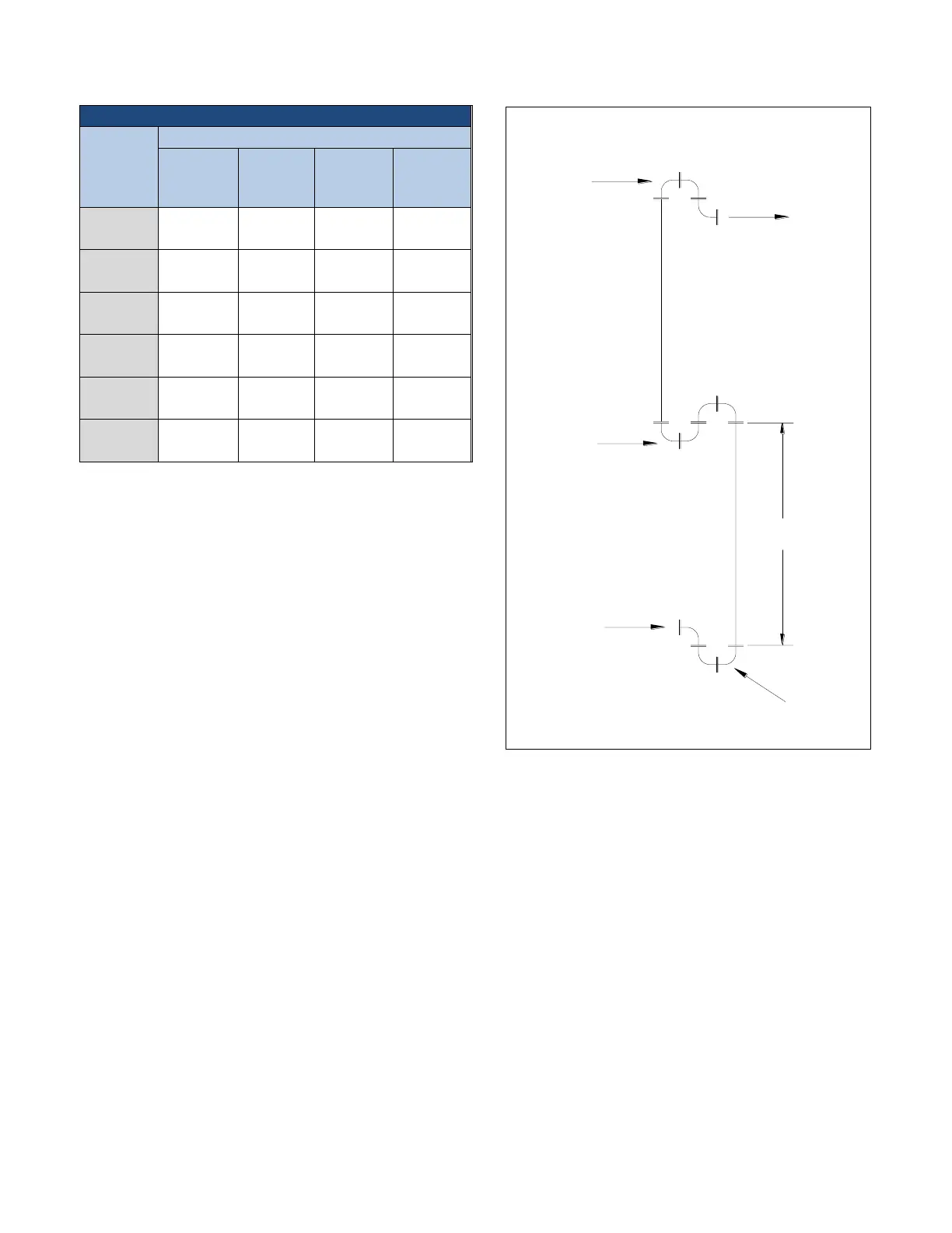
Table 6 – Liquid Line Sizes for R410A (continued)
Total
Equivalent
Length
(Ft)
Liquid Line Size (Inch OD)
Discharge (Hot Gas) Line Sizing
The discharge line sizes depend on the velocity
needed to obtain sufficient oil return. It is very
important to minimize line length and restrictions to
reduce pressure drop and maximize capacity.
Upflow hot gas risers need to have a trap at the
bottom and reverse trap at the top. In addition, a
trap and reverse trap arrangement needs to be
spaced every 15 feet in the rise for oil management
(see Figure 35).
The discharge lines should pitch downward, in the
direction of the hot gas flow, at the rate of ½ inch
per each 10 foot of horizontal run. If the chiller unit
is below the condenser, loop the discharge line to at
least 1 inch above the top of the condenser. Install a
pressure tap valve at the condenser to facilitate
measuring pressure for service. Take careful
consideration in the design of the discharge gas
riser.
Figure 35 – Vertical Riser Traps
Check the oil-level sight glass in the compressor if
trapping of oil in the piping is suspected. The chiller
is equipped with hot-gas bypass capacity control
and the gas in the upflow discharge lines may have
problems moving the oil against gravity when
completely unloaded is a single rise system is used.
We recommend a double riser system to ensure
proper oil return under low load operation. See
Figure 36 and Table 8 for double riser constructions.
FROM
CHILLER
15'
TO
CONDENSER
TRAP &
REVERSE
TRAP
(4 LR STREET ELS)
REVERSE
TRAP
(3 LR STREET ELS)
REVERSE
TRAP
(3 LR STREET ELS)
VERTICLE UPFLOW
DISCHARGE RISER
 Loading...