Manual 0-2805 5-5 SERVICE
4. Faulty components in unit
a. Return for repair or have qualified technician
repair per Service Manual.
J. Torch cuts but not adequately
1. Current set too low
a. Increase current setting.
2. Torch is being moved too fast across workpiece
a. Reduce cutting speed (refer to Torch Instruction
Manual supplied with torch).
3. Excessive oil or moisture in torch
a. Hold torch 1/8 inch (3 mm) from clean surface
while purging and observe oil or moisture
buildup (do not activate torch).
5.05 Power Supply Basic Parts
Replacement
WARNING
Disconnect primary power to the system before dis-
assembling the torch, leads, or power supply.
This section describes procedures for basic parts replace-
ment. For more detailed parts replacement procedures,
refer to the Power Supply Service Manual.
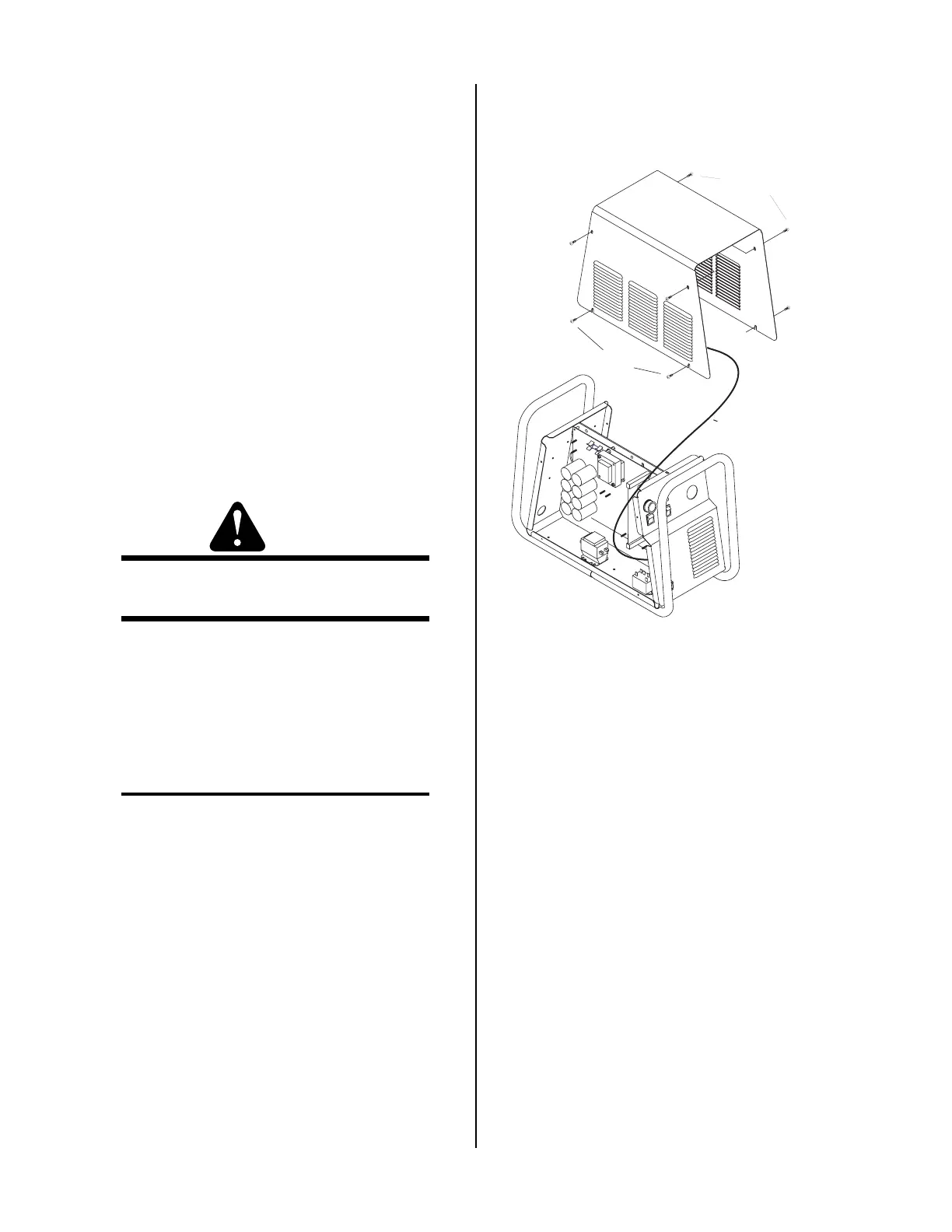
A. Cover Removal
1. Remove the upper screws which secure the cover
to the main assembly.
NOTE
There is a ground wire connection to the inside of
the unit. There is no need to disconnect the ground
wire, unless there is a need for more room to work.
2. Loosen, but do not remove, the lower screws,
then carefully pull the Cover up and away
from the unit for access to the inside of the
unit.
A-02776
Lower screws
Upper screws
Ground wire
Cover Removal
3. To reinstall the cover, complete the follow-
ing:
a. Reconnect the ground wire, if necessary.
b. Place the cover onto the frame so that it
rests on the lower screws.
c. Tighten lower screws.
d. Reinstall and tighten the upper screws.