16
For more information or to place an order visit www.thermaxaf.com
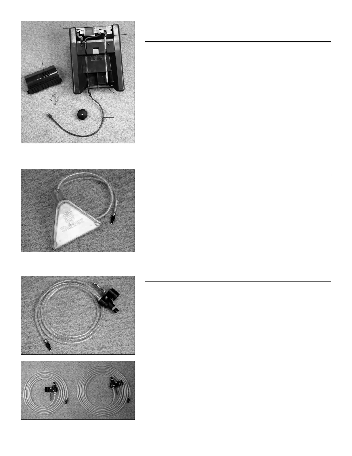
Steam Cleaning Solution Tank with
Built-in Pump Parts Diagram
1. Pump Housing 01-500-00
2. Vented Cap 24-302-001
3. Pump Housing Screw 05-054-00
4. Pump, 55 PSI 02-180-00 (120v)
5. Pump, 55 PSI 02-180-01 (230v)
6. Solution Hose Assembly 20-019-012
7. Power Cord Assembly 27-005-000
8. Panel Disconnect 03-400-00
Steam Head Assembly
MAINTENANCE/CLEANING INSTRUCTIONS: Periodically flush
with hot water to remove dirt and debris.
1. Steam Head Assembly 35-400-000
(with plastic disconnect)
Trigger Spray Valve Assembly
MAINTENANCE/CLEANING INSTRUCTIONS: Flush hose with
warm water after each use. Make sure water has completely drained from
valve and hose prior to storage.
1. 10” Solution Hose & Spray Valve Assembly 29-567-209
2. 14” Solution Hose & Spray Valve Assembly 29-562-214
3. 20” Solution Hose & Spray Valve Assembly 29-562-220
(All include plastic disconnect)
2 3
1
1
2
3
7
8
6
4