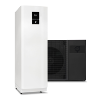
6.5 Mandatory connections (for iTec XT Standard, see additional picture below)
UV resistant, shielded, twisted pair (2, or 4 wire to include flow guard control) for outdoor use. Maximum cable length is 30 meter.
INDOOR UNIT OUTDOOR UNIT
F2
L1:1
L1:1
101.2
101.1
101.4101.3
101.6101.5
101.16
101.8
102.4102.3
102.2102.1
102.6
102.5
102.8
102.7
L1
N
L1
N
N
N
N
N
COM
110
111
113
114
116.1
118.1
COM
COM
COM
COM115
116.2
COM
119.3 119.2
118.5 118.4
COM 119.4
COMCOM
BUS_ABUS_B
CN80.1 CN80.2
CN80.1 CN80.2
121.3
121.5
121.1
GND
119.1
COM
118.3
118.2
1. Snap-on ferrite, to shield possible interference to the communication sig-
nal.
2. Cable has to be UV resistant, shielded, twisted pair (2, or 4 wire to include
flow guard control) for outdoor use and no more than 30m long.
3. Attach the cable shield to the ground screw next to the terminal in the out-
door unit, and to "COM" on the indoor terminal.
Position number Description
5 Outdoor unit communication (BUS_A to F1 / BUS_B to F2)
50 Outdoor sensor (118.5 / COM)
71 Flow guard (CN80.1 to F3 / CN80.2 to F4)
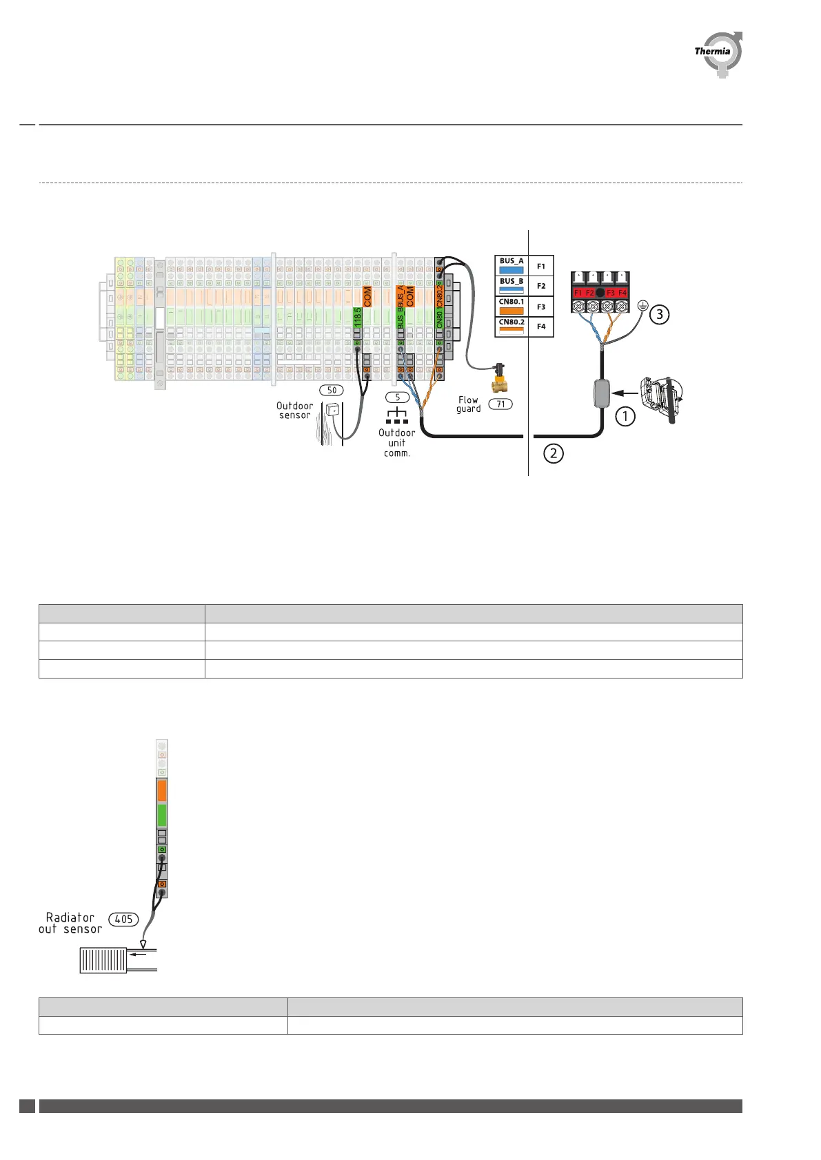
Additional mandatory connection for iTec XT Standard:
Position number
Description
405 Radiator out sensor (110 / COM)
Installation Guide iTec XT
AWIXT01IG0102 Thermia AB
48
 Loading...