15
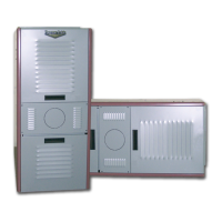
COUNTERFLOW
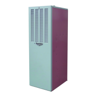
CHAMBER RETAINER
FR ONT FLU E MODELS S HOWN
SHOWN WI T H WARM AIR
OUT LET ON L EFT END
HORIZONTAL
OVERFIRE DRAFT
ACCESS COVER
OVERFIRE DRAFT
ACCESS PORT
NUT & WASHER
(4) PLACES
BURNER MOUNTING PLATE
BURNER MOUNTING
PLATE GASKET
COMBUSTION CHAMBER
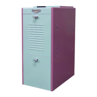
CHAMBER RETAINER
OVERFIRE DRAFT
ACCESS COVER
OVERFIRE DRAFT
ACCESS PORT
NUT & WASHER
(4) PLACES
BURNER MOUNTING PLATE
BURNER MOUNTING
PLATE GASKET
CHAMBER RETAINER
COMBUSTION CHAMBER
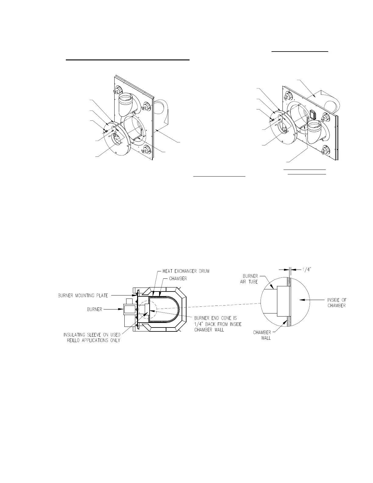
chamber during shipping and helps to maintain insertion depth. DO NOT remove
this retainer when installing burner. (Refer to Fig.3).
Fig. 3: Burner Mounting Plate for Counterflow and Horizontal Installations
When mounting the burner, (Fig 4) do not allow the burner tube or end cone to
physically touch or protrude into the chamber, as excess heat transfer could
result in destruction of the tube, end cone or both. The burner tube/end cone is
properly positioned, when the end is ¼ inch back from the inside surface of the
combustion chamber wall. A fiber insulating sleeve is provided with the Riello
BF3 Burner.
Fig. 4: Burner Insertion Illustration (Top view)
The oil burner provided with this furnace requires initial inspection, set-up, and
proper adjustment. Refer to this manual and the oil burner manufacturer’s
operating instructions for detailed information on the following items.
Initial firing of burner
Adjusting the burner combustion air
Adjusting the fuel pump pressure
Setting the draft control