18
Control Panel Connections
Removing The Control Panel
Before removing the control panel insure that the
MAINS SUPPLY is switched OFF. Either remove fuse
F1 from the power supply or shut down power source
to the metal detector.
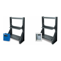
The control panel is mounted on the search head
( or remote box ) with four mounting bolts. Remove
these bolts to gain access to internal connectors.
The power supply and search head cables are wired
into 'quick disconnect' connectors. It is not
necessary to remove the wires from these connectors.
When removing the connectors be careful not to pull
on the wires, pinch the connector and pull.
Figure 19
Installing The Control Panel
When installing the control panel repeat the above
instructions in reverse order.
Note:
Care must be taken to insure that the search
head connector is fitted
correctly.
Figure 20
S/H Connector
I/P REF 1
AN. GROUND
I/P REF 2
C/NC
OSC. REF A
+ 24 VDC
1
2
3
4
5
6
Green
To
Cable: Belden 9873
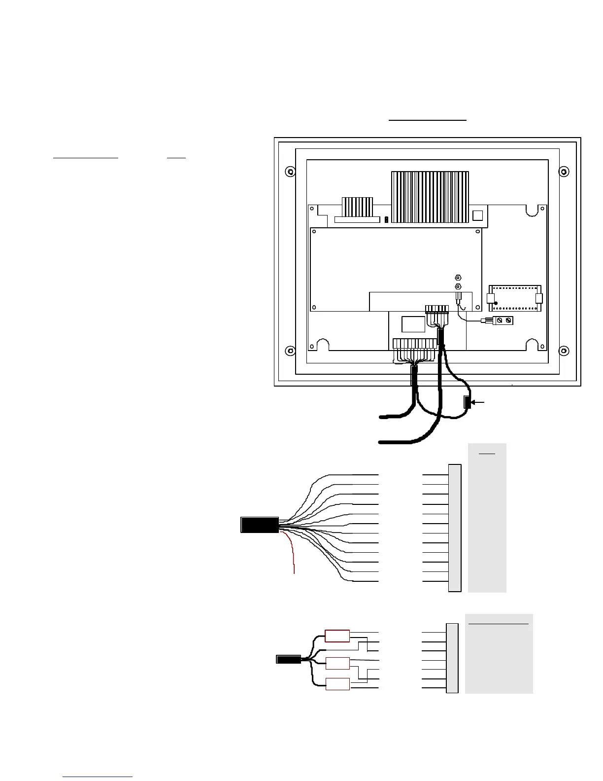
Figure 21
Eprom Socket
Search Head Connector
Power Supply Connector
DSP 2 Control Panel
( Back View )
Ground Connector
Inside Control Box
( Pull Disconnect )
PL3
24 VA
AGND
REJ
FAULT
EMU
RCHK
7V
DGND
IO 1
IO 2
RX
TX
1
2
3
4
5
6
7
8
9
10
11
12
Red
Black
Orange
Red/Blk
Blk/Wht
Org/Blk
Wht/Blk
Grn/Blk
Blu/Blk
To
Control
Panel
To Case
Ground
Cable: Belden 9261