29
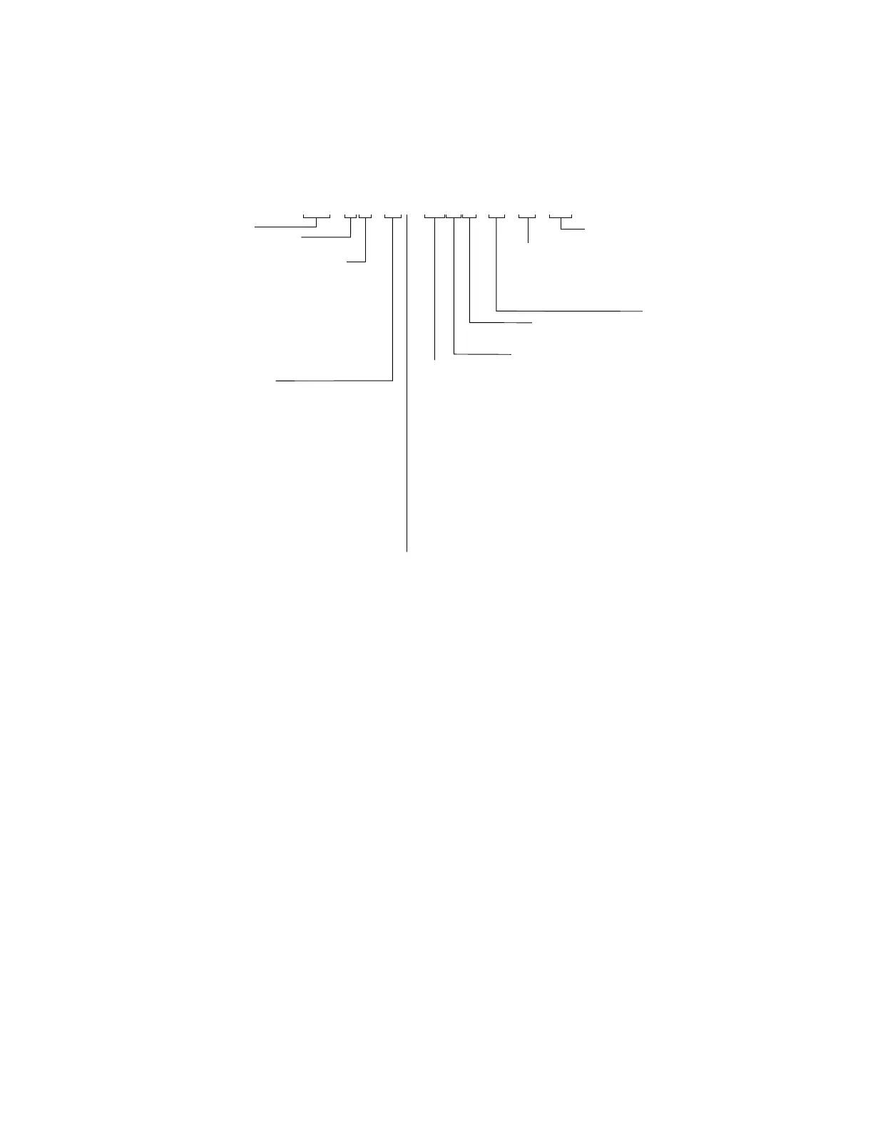
PRODUCT REFERENCE LEGEND
Genesis Controller Series
1
Heat Trace
Control
Relays
18
36
54
72
Heat Trace Control Relays
S1 = Solid State Single Pole
S2 = Solid State Two Pole
M1 = Mechanical Single Pole
M2 = Mechanical Double Pole
Enclosure Type
SS = Stainless Steel Type 4X/IP66
PS = Painted Steel Type 4/IP66
SSP = Stainless Steel Type 4X/IP66 (with purge)
PSP = Painted Steel Type 4/IP66 (with purge)
X = Custom
2
Trace Heater
Operating
Voltage(s)
100 Vac
120 Vac
200 Vac
208 Vac
220 Vac
230 Vac
240 Vac
277 Vac
480 Vac
600 Vac
Amperage Rating for
Control Relays
RTD
Inputs
18
36
54
72
108
144
Distribution
ND = No Distribution
MBx/BF y/z = Main Breaker/Breaker Frame Capacity/
Number of Breakers
Thermon Part Number
Location
O = Ordinary Locations
H1 = Class/Division Hazardous
Locations (NoAm Norms)
H2 = Ex Explosive Atmospheres
(ATEX or IECEx)
Enclosure Size
("H) x ("W) x ("D) [(mm H) x (mm W) x (mm D)]
A = 36 x 30 x 16 (914 x 762 x 406)
B = 48 x 36 x 16 (1219 x 914 x 406)
C = 60 x 36 x 16 (1524 x 914 x 406)
D = 60 x 36 x 24 (1524 x 914 x 610)
E = 60 x 48 x 24 (1524 x 1219 x 610)
F = 72 x 36 x 16 (1829 x 914 x 406)
G = 72 x 36 x 24 (1829 x 914 x 610)
J = 72 x 48 x 24 (1829 x 1219 x 610)
H = 72 x 60 x 24 (1829 x 1524 x 610)
I = 72 x 72 x 24 (1829 x 1829 x 610)
X = Custom
2
Notes:
1. Other options for the Genesis Controller, such
as installations in conditions below -40°F
(-40°C).
2. Contact Thermon for additional information.
TNG - 1836 - SSD - 120S130 - H1 - ND - P/N