7
• For simplicity it is best to have one (1) RTD sensor per control circuit for Line-Sensing Control, and the
number of DTM's will match the number of DCM's.
• "RTD Mapping” is required to monitor multiple RTD temperature sensors for a common heater. Up to twenty
(20) RTD sensors can be assigned to a heated line or surface, in which case there could be more DTM's than
DCM's. The HMI's temperature reading display shows control RTD temperature. The lowest temperature is
displayed when readings from all RTD's are below the High Alarm set point, and the highest temperature is
displayed when any RTD reading exceeds the High alarm set point.
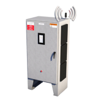
3.1.4: The IOM
The IOM (Input-Output Module) is a DIN rail mountable input/output
module. It's designed to receive inputs and outputs determined by
the requirements and design of the system. There will be at least one
(1) IOM for a Genesis Controller to provide system fault and common
alarm output.
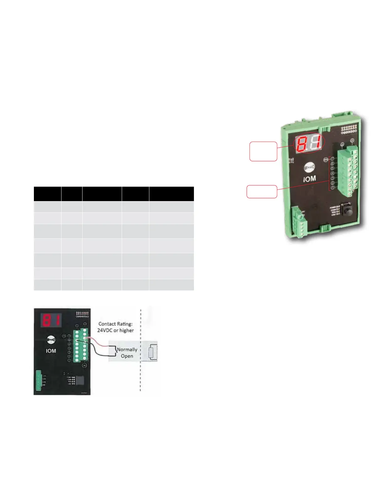
IOM Inputs
The inputs on the IOM are labeled 5 and 6. Input is
switched to ON when an external relay contact is
closed. It remains OFF when the external control relay
is open.
To use an IOM input, wire the appropriate relay as pictured in the diagram.
Load Shed is programmed to input channel 5. This function allows
an external device to control the selected circuits with Load Shed
option enabled to turn the heater off. The Load Shed option is
found in Circuit Settings. Warning: The circuit will switch back to
Enable and turn on the heater when the circuit condition is in Low
Temperature Alarm.
Force On is programmed to input channel 6. This function allows
an external device to control the selected circuits with Force On
option enabled to override other settings and turn the heater on.
The Force On option is found in Circuit Settings. Warning: The
circuit will switch back to Enable and turn off the heater when the
circuit condition is in High Temperature Alarm.
IOM Outputs
The outputs on the IOM are labelled 1-4 plus 7. Output 7, (SYS), is a non-configurable output for system fault
alarm.
To use an IOM output, wire the appropriate relay as pictured in the diagram. Each output is designed to drive
an interposing relay ≤ 24 Vdc with < 100 mA for local or remote alarms. (For specific ratings, consider a Phoenix
PLC-RSC-24DC/2 l/EX, or equal.)
The IOM input/output channels function are fixed and not configurable.
Default I/O Configuration
IOM
Sub-address
I/O Default LED State
Alarm LED
State
Function
1 Output ON OFF Common Alarm
2 Output ON OFF Circuit Trips
3 Output ON OFF HIgh Temperature Alarm
4 Output ON OFF
Low Temperature Alarm/
RTD Fault
5 Input -- --
Load Shed
(Force Off)
6 Input -- -- Force On
7 Output ON OFF System Fault Alarm
IOM
Two-digit
address for
IOM module
IOM
Sub-address