9
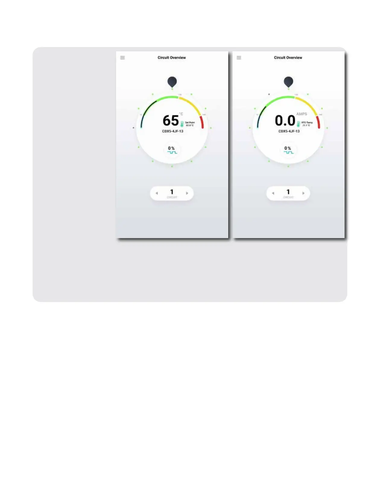
3.2.1: Circuit Overview
Provides a quick status
of all circuits at a glance
while highlighting one
circuit a time with more
detail. Each dot around
the perimeter of the
selector dial represents
one circuit. Circuit 1 is at
the top of the dial and
circuit numbers ascend
clockwise around the dial.
• Red dots represent
circuits in active alarm.
• Yellow dots represent
circuits with
acknowledged alarm.
• Green dots represent
enabled circuits with
no alarms present.
• Grey dots represent
disabled circuits.
To move between circuits,
touch the circuit dot, drag
the black selector around
the dial or use the arrows
on either side of the circuit
number. The center of the
dial displays the highlighted circuit’s live temperature, maintain temperature, circuit name, and on-off duty
cycle. Touch anywhere inside the dial to enter that circuit’s dashboard.
A slightly different view for circuits set for ambient control emphasizes electrical current (amps)
measurement versus present temperature. To change the display to show ambient control, the assigned
ambient RTD must also be identified through the RTD list in Global Settings.
Note: Temperature shown for line sensing
control method.
Note: Operating current shown for ambient
sensing control method.
3.2 The Genesis Controller HMI Screens
The following section details configuration of the Genesis Controller HMI module.