4
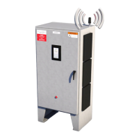
Section 1: Genesis Controller
Introduction and Overview
The following serves as a general guide and
overview on the installation, startup, operation, and
maintenance of a Genesis Controller heat tracing
control panel. This guide is to be sent in conjunction
with the project specific panel drawings and any
other installation instructions/guides and standards
provided. In the unlikely event that a conflict or
uncertainty arises, contact the Thermon engineering
support personnel assigned to this project to clarify.
NOTE: All personnel should be properly trained
and qualified to safely install, service, operate, and
program this heat tracing control panel as well as
to install, operate, and maintain all associated heat
tracing.
Section 2: Panel Inspection, Field
Connections and Internal Wiring
A typical Genesis Controller may include electrical
distribution (optional main breaker with branch
breakers for each electrical heating circuit, either
within the Genesis Controller or in an adjacent
electrical distribution enclosure. (Refer to the project
specific drawings for each panel.)
Wide varieties of Genesis Controller panel
configurations are possible and can be located in
site locations having electrically classified areas and/
or ordinary locations. The actual panel markings
provided with the panel will detail the approvals for
the specific location of the panel.
2.1: Recommended Visual Inspection Procedures
• Inspect door and/or solid state heat sink gaskets
for water intrusion as indicated by mineral deposits
and rust. Where feasible replace any gaskets which
appear to be faulty.
• Survey panel exterior and interior for dust, lint,
moisture, or foreign residue. Remove any such
residue with a lint free cloth material. Heavy
residues may be addressed with wood scrapers and
a cleaning agent. Do not soak parts with cleaning
agent but only use dampened cloths in removing
heavy residues. Excessive application of cleaning
agents can damage components.
• Check for panel corrosion and scratches. Remove
corrosion and prepare any damaged areas with
sandpaper. Repaint with the approved primer and
touch up paint.
• Check door hinges, latches, and other moving parts
for proper operation. Use machine oil to lubricate
the moving parts and restore proper operation
where necessary.
• Check for mechanical damage to any windows as
well as check the window seals. Repair or replace
damaged materials. In all cases where equipment
damage is observed, a root cause analysis should
be initiated to determine any future corrective
action needed to prevent a recurrence.
2.2: Wiring and Connections Survey
• The wiring and connections survey recommended
is as follows:
• If the servicing of removable electrical connectors is
to be conducted, then make certain the area is free
of explosive atmospheres.
• If equipment is available, an infrared scan of the
interior of the panel cabinet and associated wiring
(during operation) is recommended.
• Any unusually high temperatures at connections
are usually evidence of poor connections. Tighten
connections, repair with new terminations, and/or
replace any components which have been exposed
to long term overheating. All terminal block
connections should be tightened using a torque
indicating screwdriver to the levels indicated in
Table 1 and project installation drawings.
• Check for corrosion at electrical connections
and terminations. Where corrosion of electrical
terminals is observed, this may be additional
evidence of loose connections and excessive heat. A
part replacement may be necessary.
• Inspect wiring for abrasion wear, mechanical
damage, and thermal overexposure. Repair or
replace any damaged or defective wiring. In all
cases where equipment damage is observed, a root
cause analysis should be initiated to determine
any future corrective action needed to prevent a
recurrence.
2.3: Control System Operation Check
The Genesis Controller controller screen is an ideal
resource in facilitating operation checks of the control
system. To begin this program, energize the panel
and the appropriate heat trace circuits for a minimum
of 24 hours or until all circuits are cycling within their
appropriate control band. A typical list of operational
maintenance checks is available for a successful
installation of a Genesis Controller heat tracing control
and monitoring panel, a number of equally critical
parts of the system must be installed properly. Areas
requiring close attention are:
• The heat trace and insulation
• The RTD temperature sensor installation
• The distribution of the field RTD and power wiring
• The installation and routing of wiring inside the
panel.
Note: The heat tracing system installation shall be
in accordance with the electrical area classification
requirements as well as shall conform to the
latest requirements as detailed in applicable heat
tracing standards, the local Electrical Code and
plant standard practices. Where conflicts arise,
contact the project engineer for resolution.

 Loading...