5
2.4: Heat Trace and Insulation Installation
All heat trace circuits and insulation shall be installed in accordance with project installation details provided.
In addition, refer to the Electric Heat Tracing Maintenance and Troubleshooting Guide (Thermon Form No.
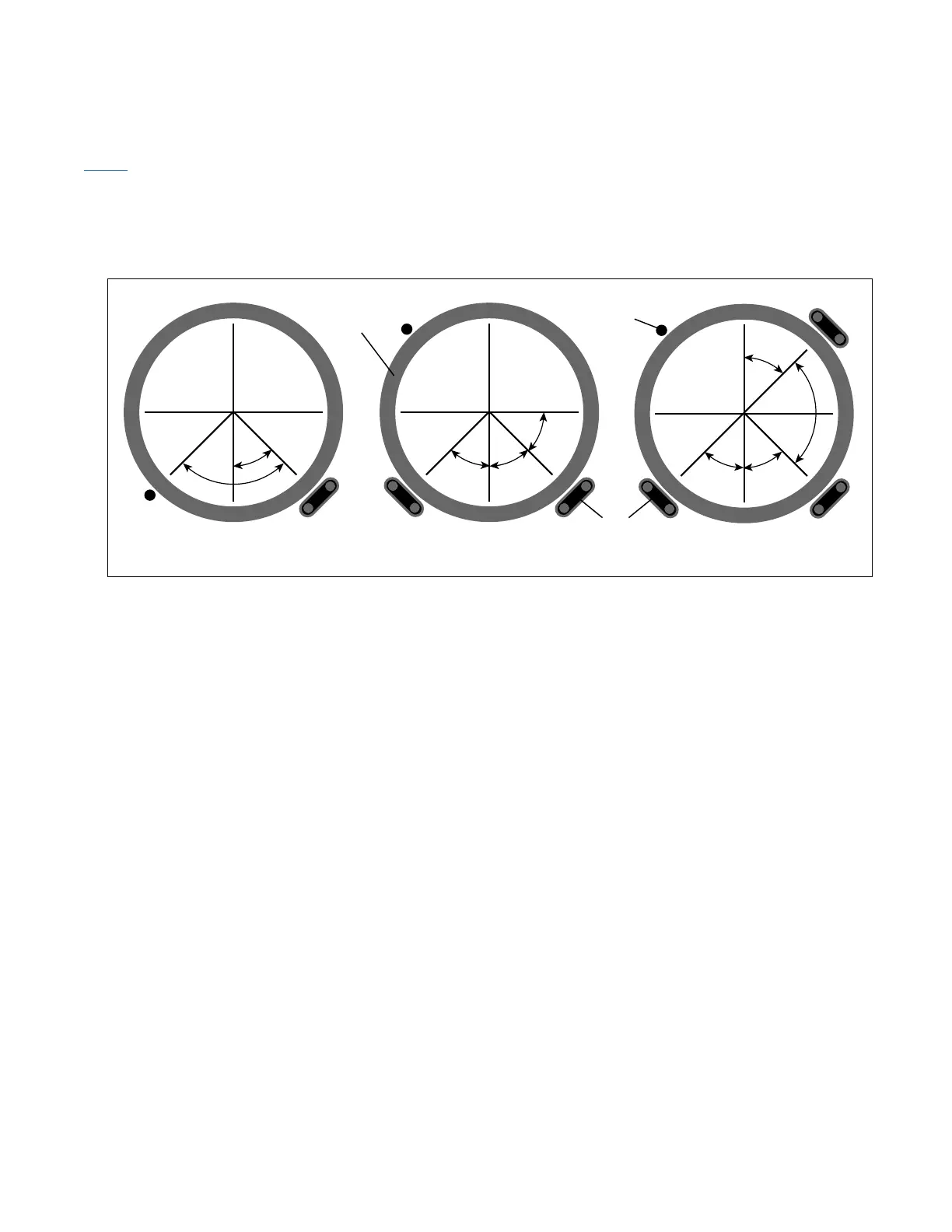
20745) for general procedures and installation tips. RTD Installation and Wiring RTD control sensors should
generally be installed on the process lines (see figure below) or in ambient (where ambient sensing is applied)
in a location that is most representative of the entire heat trace circuit. In general, it is recommended that the
sensors not be located at heat sinks such as pipe supports, pumps, and valves as the control system response
needs to be based on the majority of the process line.
2.5: Power Distribution Wiring and Breakers
All field power wiring materials used shall be suitable for the intended service and shall be rated for insulation
service temperatures up to and not exceeding 221°F (105°C) unless otherwise higher values are noted in
project specifications. Circuit breakers (if not already supplied in the panel) should be selected based on the
heat trace type being used, the service voltage, and the circuit current draw characteristics. It is especially
important when using self-regulating heat trace to make sure that the circuit breaker response curve type
is coordinated with the startup characteristic of the heat trace cable in a cold start condition. All distribution
wiring connections should be tightened using a torque indicating screwdriver to the levels indicated below.
Recommended Torque Values (Typical)*
Solid State Relays on Heat Sink (where used): 12.5–13.5 in. lbs. (1.41–1.53 Nm)
Distribution Equipment: 13.2–15.9 in. lbs. (1.49–1.8 Nm)
* Required torque values may vary depending on individual panel designs and size of terminals. Refer to
project documentation for additional information.
2.6: Panel Wiring
Genesis Controller panels are configured and pre-wired into an integrated heat trace control and monitoring
system. Clean terminal strips are provided to facilitate the field wiring into the panels. Refer to the project
specific panel drawings when installing the field wiring within the panel. All terminal block connections
should be tightened using a torque indicating screwdriver to the levels indicated, including terminal block
connections to/on Genesis Controller modules. All heat trace circuits should be properly terminated and
meggered prior to energizing the heat trace power distribution and control panels. In addition, all pipes should
be insulated and weather sealed to achieve the expected heat-up and temperature maintenance performance
of the system.
Heating Cable
(Typical)
Pipe Wall
Temperature Sensor
(Typical)
45°
45°
45°
45°
45°
90°
45°
45°
90°
Single Trace Installation Triple Trace InstallationDual Trace Installation
RTD Sensor Location On Piping