1-14
C4362
C4352
GEAR PUMP 1.2
Assembly 137/153 (cont’d)
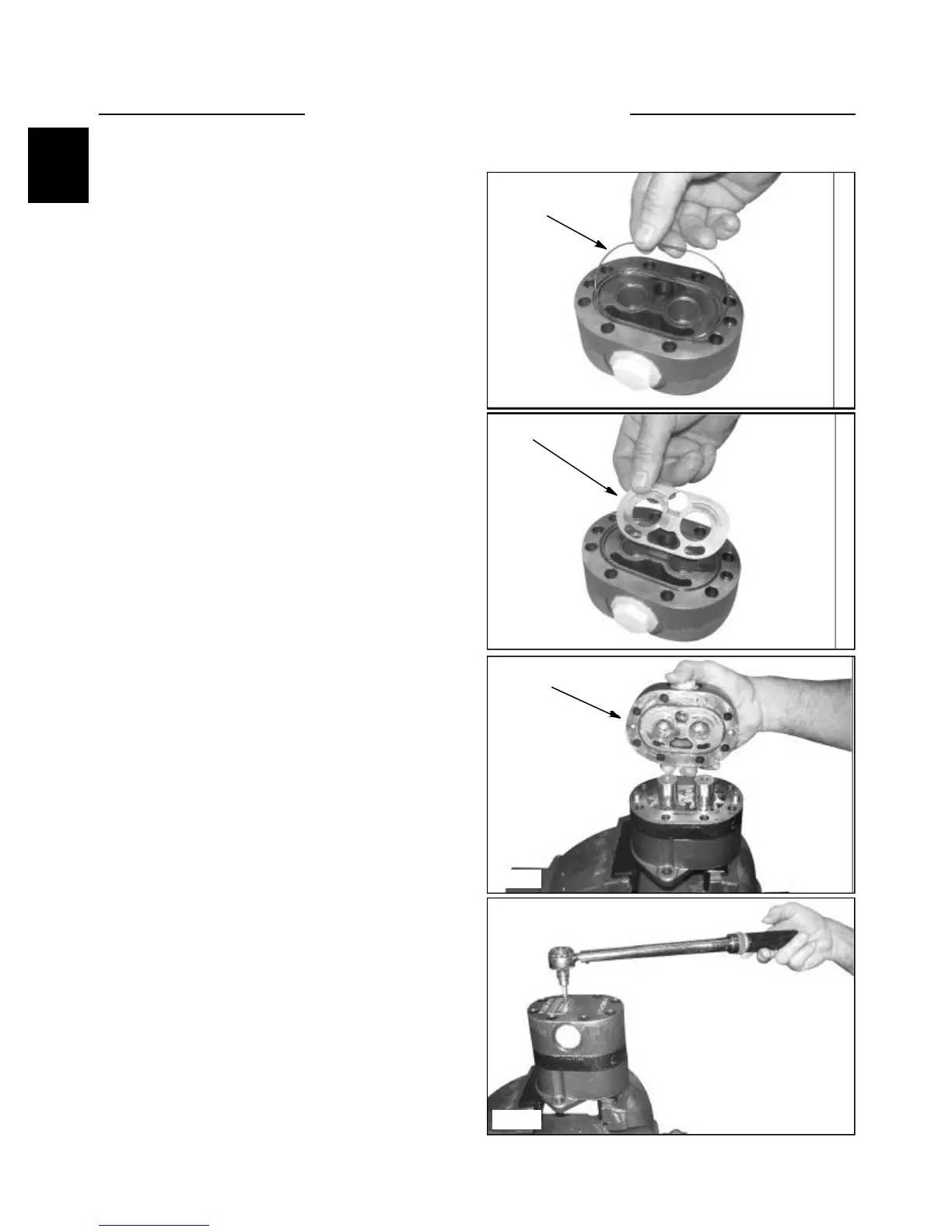
10. Place the cover assembly on a bench with the
machined surface facing up. Place the rubber seal
ring in the cover seal ring groove. (fig C4362)
11. Find the wear plate with the 0.625” diameter
pressure hole and two oblong holes on the inlet side.
Position the wear plate in the cover with the bronze
side facing up (towards gears) and the 0.625”
pressure hole located over the circular holes in the
cover. (fig. C4352)
12. Line up the cover assembly with the shaft
journals and dowel pins (fig. C4351). Lightly tap the
back of the cover until dowel pins are completely
engaged. Check the seal making sure it is seated
properly with no foreign material pinched between
the surfaces.
13. Place the screws in the cover holes and turn until
the treads engage. Use care so that cross threading
does not occur.
14. Torque the four bolts in a crossing pattern a little
at a time until you reach the final torque of 47 ft lbs.
(65 Nm) (fig. C4363)
15. After the pump has been disassembled and
reassembled it it suggested that the pump be run in
and tested on an appropriate test stand. This is done
to verify the volumetric efficiency and the integrity
of the unit.
Seal ring
C4351
C4363
Wear plate
Cover assembly