1-13
C4356
C4353
GEAR PUMP 1.2
Assembly 137/153 (cont’d)
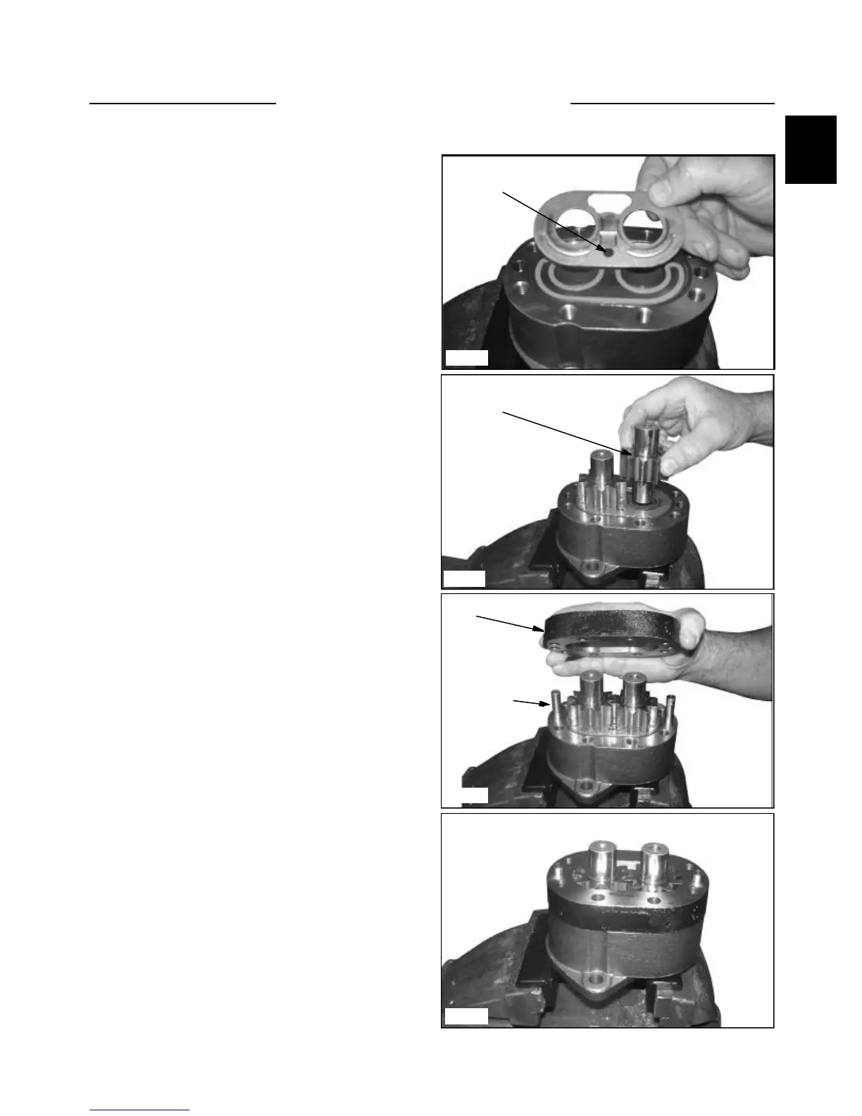
6. Place the load seal directly on top of the pre-load
seal (blue E-ring).
7. Find the wear plate with a 0.25” diameter
pressure hole and no oblong holes on the inlet side.
Place the wear plate on top of the load ring with the
bronze side facing up towards the gear. The 0.25”
pressure hole is to be positioned on the E-ring side of
the body. (fig C4356)
8. Lubricate the spline end of the drive shaft with
Aerolube grease. Insert the drive shaft in the correct
bearing bore. Align the idler shaft with the assembly
marks to ensure assembly is installed with the same
orientation as before assembly. Place the idler shaft
in the correct bearing bore into the body (fig.
C4354). Inspect gear teeth for alignment.
Misaligned gear teeth may increase operating noise.
Lubricate the complete gearset using clean light oil.
9. Insert the two dowel pins into the body
assembly. Place the gear plate over the dowel pins
and lightly tap making sure it contacts the body. (fig.
C4353) Check to make sure the gear plate is seated
properly with no foreign pinched between these
surfaces.
Wear plate with
0.25” pressure hole
C4354
Idler shaft
C4361
Dowel pin
Gear plate
Check seal