7
2.2 CONTROL PANEL
The THOMAS Mini-Skid Loader features two
independent hydraulic systems for the Mini-Skid
Loader and attachment operation.
Each of these systems is powered by either or both
hydraulic pumps. The primary pump provides
larger oil flow, while the secondary pump produces
lower flow.
One system is dedicated to hydraulic motor driven
attachments only, while the second system controls
all other Mini-Skid Loader functions. The pumps
can be switched back and forth between the two
systems or diverted as the need arises.
For example, for normal operation, one would have
the large displacement pump operating the Mini-
Skid Loader functions. However, if one was
operating an attachment with a hydraulic motor,
one would switch the circuits so that the large
displacement pump was operating the attachment,
while the smaller pump was operating the Mini-
Skid Loader, thus allowing the operator to drive
slowly while providing maximum power to the
attachment.
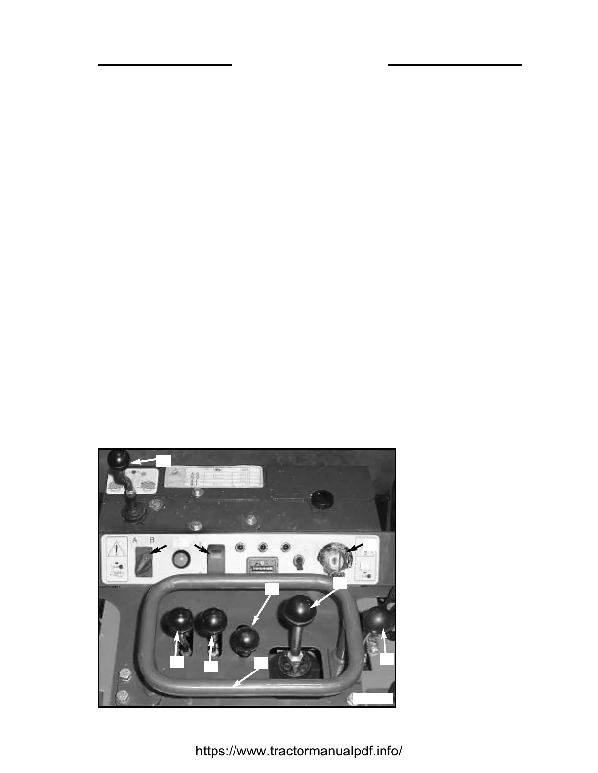
All functions are controlled from the top console of
the mini-skid as shown in Fig. 2.2.
OPERATOR AREA CONTROLS (Fig. 2.2)
1. Throttle
2. LH Drive Lever
3. RH Drive Lever
4. Auxiliary Lever, Cylinder Driven Attach.
5. Lift & Tilt Joystick
6. Handle Grip
DASH PANEL CONTROLS (Fig. 2.2)
7. Pump Selector Switch
8. Auxiliary Lever, Motor Driven Attach.
9. Key Switch
10. Speed Regulation Switch
Throttle Control
The throttle control is on the right hand side of the
operator area controls (Item #1 in Fig. 2.2). When
the throttle control is set fully back the engine is at
idle speed. Moving the throttle control forward
increases the engine speed. The machine should
always be operated with the throttle fully open.
Before shutting off the engine, return the throttle
control to the idle position and allow the engine to
cool for at least 2 minutes.
Steering Controls
The THOMAS Mini-Skid Loader features single-
hand steering. For normal
operation, the most
comfortable hand position is
to operate the steering levers
with the palm of the left
hand, with the fingers
gripping the grip handle.
This position will allow for
better control of the unit. At
the same time, the right hand
should grip the grip handle
for operator stability, but can
also be used to operate the
lift and tilt joystick as
required.
Flexing the fingers will allow
forward travel, and simply
rotating the palm will allow
normal steering.
(Steering Controls
continued on page 6)
2. CONTROLS
Fig. 2.2
1
2
3
4
5
6
8
7
10
9