17
3. OPERATION
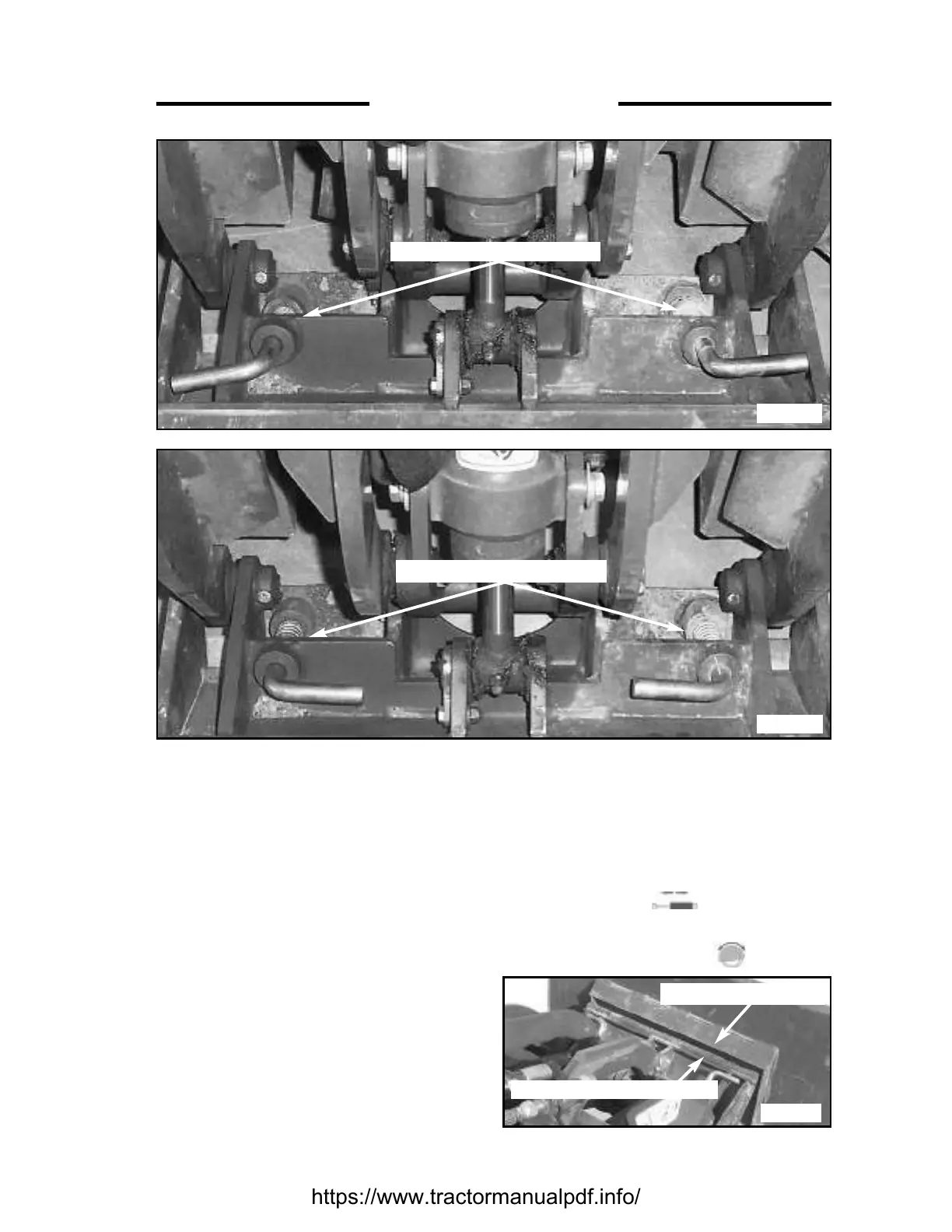
Fig. 3.2B
ATTACHMENT FRAME
ATTACHMENT LIP
C4195
LOCK PINS DISENGAGED
LOCK PINS ENGAGED
C4221
C4222
Fig. 2.5
Fig. 2.5A
5. Rotate the lock pins to the locked position
(handles facing inwards) (Figs. 3.2A), and
check that the lock pins are fully inserted
through the lock holes in the attachment.
6. Connect attachment hydraulic hoses (if
required) to the quick couplers. (Fig. 3.2C)
7. Using the couplers on RH side of the Mini-Skid
Loader (marked ) are for cylinder
operated attachments and the couplers on the
LH side of the Mini-Skid Loader are for motor-
driven attachments (marked ).
3.2 MOUNTING ATTACHMENTS
The quick-tach, which is standard equipment,
allows changing from one attachment to another
quickly without having to remove bolts or pins.
INSTALLATION OF ATTACHMENT
1. Rotate lock pins to the unlock position (handle
pointing outward). (Figs. 3.2)
2. Tilt the attachment frame forward so that the
top round edge of the attachment frame will fit
under the lip on the attachment. (Fig. 3.2B)
3. Drive into the attachment, raising the arms so
that the top of the attachment frame slips under
the lip on the attachment, and the attachment
lifts slightly.
4. Using the tilt cylinder, roll back the attachment
so that it drops into place.