Chapter 1: Connections and Setup
Illustrations contained in this document are for representation only.
7
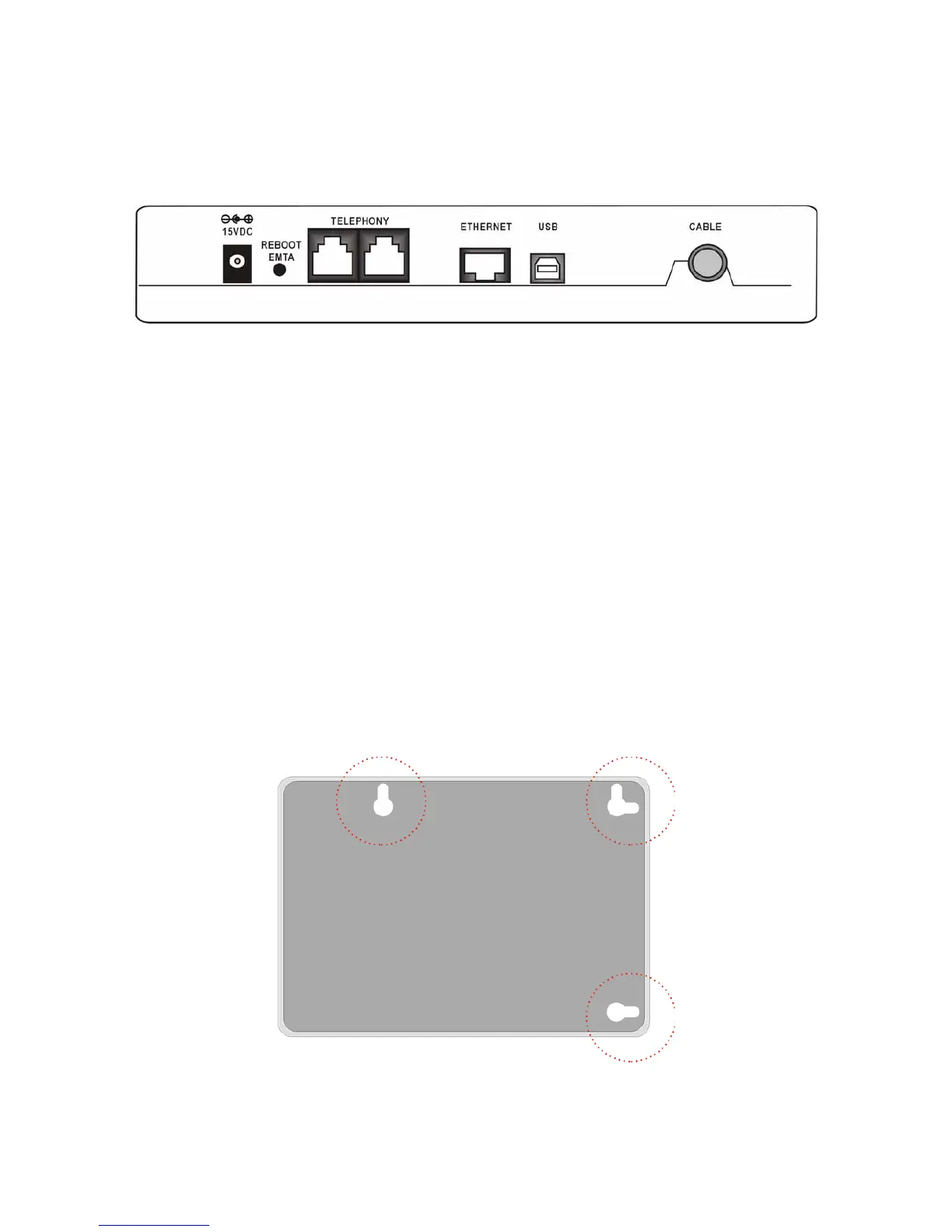
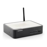
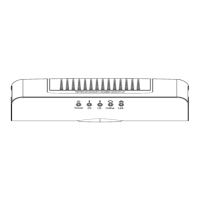
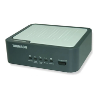
Rear Panel
15VDC: 15V Power connector
REBOOT EMTA: Reset this Voice Over IP Cable Modem to the factory settings
Telephony (LINE1/LINE2): RJ-11 Phone set connector
ETHERNET: Ethernet 10/100BaseT RJ-45 connector
USB: USB Connector
CABLE: F-Connector
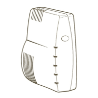
Wall Mounting
The number of the screw: 2 pcs
Direction for wall mounting: LED panel upward.
Dimension for the screw: TBD
There are 3 slots on the underside of the Cable Modem that can be used for wall mounting:
Note: When wall mounting the unit, ensure that it is within reach of the power outlet. You will
need 3 screws (4.4mm) to wall mount the unit. To do this: