Chapter 1: Connections and Setup
4
OFF FLASH MTA DHCP
FLASH OFF MTA SNMP/TFTP
MTA
initialization
FLASH FLASH RSIP
ON ON Both Lines On-Hook
ON FLASH Tel1 Off-hook, Tel2 On-hook
FLASH ON Tel1 On-hook, Tel2 Off-hook
MTA
Operation
FLASH FLASH
<CM Normal Operation>
Both Lines Off-Hook
ON FLASH FLASH FLASH FLASH FLASH FLASH
SW Download
Operation
FLASH ON From Right to Left
A software download and while updating the
FLASH memory
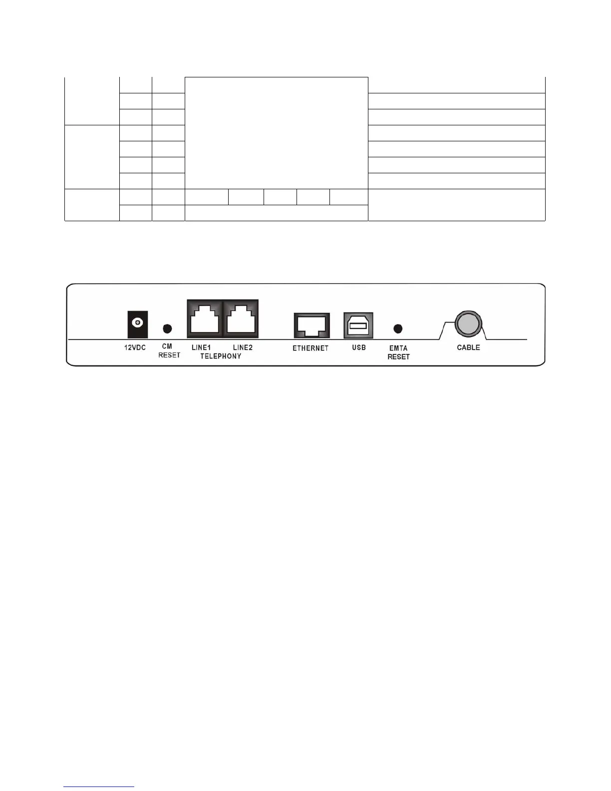
Rear Panel
12VDC: 12V Power connector
CM RESET: Reset this cable modem to the factory settings
Telephony (LINE1/LINE2): RJ-11 Phone set connector
ETHERNET: Ethernet 10/100 BaseT RJ-45 connector
USB: USB Connector
EMTA RESET: Reset this cable modem
CABLE: F-Connector
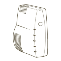
Wall Mounting
The number of the screw: 2 pcs
Direction for wall mounting: LED panel upward.
Dimension for the screw: TBD
There are 3 slots on the underside of the Cable Modem that can be used for wall mounting: